N10-007 Explain the basics of network theory and concepts
Encapsulation/de-encapsulation
While the data travels down the layers, headers are added which is known as encapsulation and removed as it travels down which is known as decapsulation. The figure given below illustrates the processes.
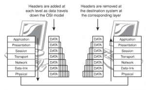
Figure 71: Encapsulation and Decapsulation
As the data travels down the decapsulation is done by the corresponding layer, which had added the information. With every movement of the information, it is sorted and arranged in logical groups of bits. A different term is used to define the process at every layer. The terms are:
| Layer Name | Term Used |
| Layer 1 | Bits |
| Layer 2 | Packets & Frames |
| Layer 3 | Packets & Datagrams |
| Layer 4 | Packets, Segments & Datagrams |
| Layer 5 | Packets |
| Layer 6 | Packets |
| Layer 7 | Packets & Messages |
Modulation techniques
Modulation is the addition of information (or the signal) to an electronic or optical signal carrier. Modulation can be applied to direct current (mainly by turning it on and off), to alternating current, and to optical signals. One can think of blanket waving as a form of modulation used in smoke signal transmission (the carrier being a steady stream of smoke). Morse code, invented for telegraphy and still used in amateur radio, uses a binary (two-state) digital code similar to the code used by modern computers. For most of radio and telecommunication today, the carrier is alternating current (AC) in a given range of frequencies. Common modulation methods include:
- Amplitude modulation (AM), in which the voltage applied to the carrier is varied over time
- Frequency modulation (FM), in which the frequency of the carrier waveform is varied in small but meaningful amounts
- Phase modulation (PM), in which the natural flow of the alternating current waveform is delayed temporarily
Modem Modulation and Demodulation
A computer with an online or Internet connection that connects over a regular analog phone line includes a modem. Combining beginning letters from the words modulator and demodulator derives this term. In a modem, the modulation process involves the conversion of the digital computer signals (high and low, or logic 1 and 0 states) to analog audio-frequency (AF) tones. Digital highs are converted to a tone having a certain constant pitch; digital lows are converted to a tone having a different constant pitch. These states alternate so rapidly that, if you listen to the output of a computer modem, it sounds like a hiss or roar. The demodulation process converts the audio tones back into digital signals that a computer can understand.
Multiplexing
More information can be conveyed in a given amount of time by dividing the bandwidth of a signal carrier so that more than one modulated signal is sent on the same carrier. Known as multiplexing, the carrier is sometimes referred to as a channel and each separate signal carried on it is called a subchannel. (In some usages, each subchannel is known as a channel.) The device that puts the separate signals on the carrier and takes them off of received transmissions is a multiplexer. Common types of multiplexing include frequency-division multiplexing (FDM) and time-division multiplexing (TDM). FDM is usually used for analog communication and divides the main frequency of the carrier into separate sub channels, each with its own frequency band within the overall bandwidth. TDM is used for digital communication and divides the main signal into time-slots, with each time-slot carrying a separate signal.
Numbering systems
Humans are accustomed to dealing with decimal numbers, while computers use binary digits. Octal and hexadecimal numbers are “short forms” for binary numbers, where each hexadecimal digit takes the place of either three or four binary digits. Since people and computers speak different “number languages”, it is often necessary to convert numbers from one of these systems to the other. If you spend any amount of time dealing with computers or networks, you will find yourself needing to do this on occasion, so it’s worth taking a quick look at how it is done.
First of all, let me say this: the easiest way to convert between decimal, binary, octal and hexadecimal numbers is to use a scientific calculator. This is what most people do, and I highly recommend it. However, there are cases where you may need to be able to do this by hand—we don’t all always have a calculator on us. Also, understanding the manual conversion process will help you comprehend more intuitively how binary, octal and hexadecimal numbers work.
Broadband/base band
Following is some information on broadband and baseband:
Baseband:
Digital signals are used
Frequency division multiplexing is not possible
Baseband is bi-directional transmission
Short distance signal travelling
Entire bandwidth of the cable is consumed by a single signal in a baseband transmission.
Broadband:
Analog signals are used
Transmission of data is unidirectional
Signal travelling distance is long
Frequency division multiplexing is possible
The signals are sent on multiple frequencies and allow all the multiple signals are sent simultaneously in broadband transmission.
Bit rates vs baud rate
Most data communications over networks occurs via serial-data transmission. Data bits transmit one at a time over some communications channel, such as a cable or a wireless path.
Bit Rate
The speed of the data is expressed in bits per second (bits/s or bps). The data rate R is a function of the duration of the bit or bit time (TB) (Fig. 1, again):
R = 1/TB
Rate is also called channel capacity C. If the bit time is 10 ns, the data rate equals:
R = 1/10 x 10–9 = 100 million bits/s
This is usually expressed as 100 Mbits/s.
Baud Rate
The term “baud” originates from the French engineer Emile Baudot, who invented the 5-bit teletype code. Baud rate refers to the number of signal or symbol changes that occur per second. A symbol is one of several voltage, frequency, or phase changes.
NRZ binary has two symbols, one for each bit 0 or 1, that represent voltage levels. In this case, the baud or symbol rate is the same as the bit rate. However, it’s possible to have more than two symbols per transmission interval, whereby each symbol represents multiple bits. With more than two symbols, data is transmitted using modulation techniques.
When the transmission medium can’t handle the baseband data, modulation enters the picture. Of course, this is true of wireless. Baseband binary signals can’t be transmitted directly; rather, the data is modulated on to a radio carrier for transmission. Some cable connections even use modulation to increase the data rate, which is referred to as “broadband transmission.”
By using multiple symbols, multiple bits can be transmitted per symbol. For example, if the symbol rate is 4800 baud and each symbol represents two bits, that translates into an overall bit rate of 9600 bits/s. Normally the number of symbols is some power of two. If N is the number of bits per symbol, then the number of required symbols is S = 2N. Thus, the gross bit rate is:
R = baud rate x log2S = baud rate x 3.32 log10S
If the baud rate is 4800 and there are two bits per symbol, the number of symbols is 22 = 4. The bit rate is:
R = 4800 x 3.32 log(4) = 4800 x 2 = 9600 bits/s
If there’s only one bit per symbol, as is the case with binary NRZ, the bit and baud rates remain the same.
Sampling size
Different approaches to sample size estimation
1. Get a convenient sample and hope it is enough
2. See how many observations other published projects included and imitate them
3. Follow a rule of thumb
4. Make a calculation based on your best assumptions.
Hope is good in many situations except this one. Imitate others is also not a good advice. What if the others did an underpowered study? Why replicate their mistake?
There are some rules of thumb such as:
- For group comparisons of means (t-test) have at least 30 in each group.
- For group comparisons of proportions (chi-square) have at least 5 in each cell.
- For regressions/correlations have at least 20 observations for each independent variable.
- For Cox regression have at least 10 times more events / end points than independent variables (suggested by Peduzzi et al). For example: you have four independent predictor variables in the model and the proportion of positive cases in the population is expected to be 0.30 (30%) the minimum number of cases required would be 133.
However, these rule of thumb are quite rudimentary because they do not consider the magnitude of the effect size or correlation you are looking for. They just give the bare minimum number you should have to avoid violating underlying mathematical assumptions but they do not consider your particular situation. The best approach to estimate the size of the sample is to do a proper sample size calculation considering the situation in your study.
Carrier detect/sense
Short for Carrier Sense Multiple Access / Collision Detection, a set of rules determining how network devices respond when two devices attempt to use a data channel simultaneously (called a collision). Standard Ethernet networks use CSMA/CD to physically monitor the traffic on the line at participating stations. If no transmission is taking place at the time, the particular station can transmit. If two stations attempt to transmit simultaneously, this causes a collision, which is detected by all participating stations. After a random time interval, the stations that collided attempt to transmit again. If another collision occurs, the time intervals from which the random waiting time is selected are increased step by step. This is known as exponential back off.
CSMA/CD is a type of contention protocol. Networks using the CSMA/CD procedure are simple to implement but do not have deterministic transmission characteristics. The CSMA/CD method is internationally standardized in IEEE 802.3 and ISO 8802.3.
TCP/IP suite
As with all other communications protocol, TCP/IP is composed of layers:
- IP – is responsible for moving packet of data from node to node. IP forwards each packet based on a four byte destination address (the IP number). The Internet authorities assign ranges of numbers to different organizations. The organizations assign groups of their numbers to departments. IP operates on gateway machines that move data from department to organization to region and then around the world.
- TCP – is responsible for verifying the correct delivery of data from client to server. Data can be lost in the intermediate network. TCP adds support to detect errors or lost data and to trigger retransmission until the data is correctly and completely received.
- Sockets – is a name given to the package of subroutines that provide access to TCP/IP on most systems.
The Internet Protocol was developed to create a Network of Networks (the “Internet”). Individual machines are first connected to a LAN (Ethernet or Token Ring). TCP/IP shares the LAN with other uses (a Novell file server, Windows for Workgroups peer systems). One device provides the TCP/IP connection between the LAN and the rest of the world.
To insure that all types of systems from all vendors can communicate, TCP/IP is absolutely standardized on the LAN. However, larger networks based on long distances and phone lines are more volatile. In the US, many large corporations would wish to reuse large internal networks based on IBM’s SNA. In Europe, the national phone companies traditionally standardize on X.25. However, the sudden explosion of high-speed microprocessors, fiber optics, and digital phone systems has created a burst of new options: ISDN, frame relay, FDDI, Asynchronous Transfer Mode (ATM). New technologies arise and become obsolete within a few years. With cable TV and phone companies competing to build the National Information Superhighway, no single standard can govern citywide, nationwide, or worldwide communications.
The original design of TCP/IP as a Network of Networks fits nicely within the current technological uncertainty. TCP/IP data can be sent across a LAN, or it can be carried within an internal corporate SNA network, or it can piggyback on the cable TV service. Furthermore, machines connected to any of these networks can communicate to any other network through gateways supplied by the network vendor.
UDP
UDP provides an unreliable connectionless communication method between hosts. UDP is considered a best-effort protocol, but it’s considerably faster than TCP. The ses- sions don’t establish a synchronized session like the kind used in TCP, and UDP doesn’t guarantee error-free communications. The primary purpose of UDP is to send small pack- ets of information. The application is responsible for acknowledging the correct reception of the data.
Collision
Instead of collision detection, as with CSMA/CD, the Carrier Sense Multiple Access with Collision Avoidance (CSMA/CA) access method uses signal avoidance rather than detection. In a networked environment, CSMA/CA is the access mechanism used in Apple’s LocalTalk network and with the 802.11 wireless standards.
On CSMA/CA networks, each computer signals its intent to transmit data signals before any data is actually sent. When a networked system detects a potential collision, it waits before sending the transmission, allowing systems to avoid transmission collisions. The CSMA/CA access method uses a random backoff time that determines how long to wait before trying to send data on the network. When the backoff time expires, the system again “listens” to verify a clear channel on which to transmit. If the medium is still busy, another backoff interval is initiated that is less than the first. The process continues until the wait time reaches zero, and the medium is clear.
Recent Comments