N10-007 Explain the basics of routing concepts and protocols
Loopback interface
You can specify a software-only interface called a loopback interface to emulate an interface. Loopback interfaces are supported on all platforms. A loopback interface is a virtual interface that is always up and allows Border Gateway Protocol (BGP) and remote source-route bridging (RSRB) sessions to stay up even if the outbound interface is down.
You can use the loopback interface as the termination address for BGP sessions, for RSRB connections, or to establish a Telnet session from the device’s console to its auxiliary port when all other interfaces are down. You can also use a loopback interface to configure IPX-PPP on asynchronous interfaces. To do so, you must associate an asynchronous interface with a loopback interface configured to run IPX. In applications in which other routers or access servers attempt to reach this loopback interface, you should configure a routing protocol to distribute the subnet assigned to the loopback address.
Packets routed to the loopback interface are rerouted back to the router or access server and processed locally. IP packets routed out the loopback interface but not destined to the loopback interface are dropped. This means that the loopback interface serves as the Null 0 interface also.
Routing loops
Routing loops can occur on networks with slow convergence. Routing loops occur when the routing tables on the routers are slow to update and a redundant communication cycle is created between routers. Two strategies can combat potential routing loops:
- Split horizon: Works by preventing the router from advertising a route back to the other router from which it was learned. This prevents two nodes from bouncing packets back and forth between them, creating a loop.
- Poison reverse (also called split horizon with poison reverse):
Dictates that the route is advertised back on the interface from which it was learned, but it has a hop count of infinity, which tells the node that the route is unreachable.
Routing tables
Before a data packet is forwarded, a chart is reviewed to determine the best possible path for the data to reach its destination. This chart is the computer’s routing table. Maintaining an accurate routing table is essential for effective data delivery. Every computer on a TCP/IP network has a routing table stored locally.
Static vs dynamic routes
In environments that use static routing, routes and route information are manually entered into the routing tables. Not only can this be a time-consuming task, but also errors are more common. In addition, when a change occurs to the network’s layout, or topology, statically configured routers must be manually updated with the changes. Again, this is a time-consuming and potentially error-laden task. For these reasons, static routing is suited to only the smallest environments, with perhaps just one or two routers. A far more practical solution, particularly in larger environments, is to use dynamic routing.
You can add a static route to a routing table using the route add command. To do this, specify the route, the network mask, and the destination IP address of the network card your router will use to get the packet to its destination network.
The syntax for the route add command is as follows:
route add 192.168.2.1 mask (255.255.255.0) 192.168.2.4
Adding a static address is not permanent; in other words, it will most likely be gone when the system reboots. To make it persistent (the route is still in the routing table on boot), you can use the switch with the command.
Dynamic Routing
In a dynamic routing environment, routers use special routing protocols to communicate. The purpose of these protocols is simple: They enable routers to pass on information about themselves to other routers so that other routers can build routing tables. Two types of routing protocols are used: the older distance-vector protocols and the newer link-state protocols.
Default route
A default gateway is the router’s IP address, which is the pathway to any and all remote networks. To get a packet of information from one network to another, the packet is sent to the default gateway, which helps forward the packet to its destination network. Computers that live on the other side of routers are said to be on remote networks. Without default gateways, Internet communication is not possible because your computer doesn’t have a way to send a packet destined for any other network.
On the workstation, it is common for the default gateway option to be configured automatically through DHCP configuration.
Distance vector routing protocols
With distance-vector router communications, each router on the network communicates all the routes it knows about to the routers to which it is directly attached. In this way, routers communicate only with their router neighbors and are unaware of other routers that may be on the network.
The communication between distance-vector routers is known as hops. On the network, each router represents one hop, so a network using six routers has five hops between the first and last router.
The tracert command is used in a Windows environment to see how many hops a packet takes to reach a destination. To try this at the command prompt, enter tracert comptia.org. Figure 47 shows an example of the output on a Windows 7 workstation.
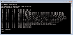
FIGURE 47: The results of running tracert on a Windows 7 system.
RIP v2
The second version of RIP dealt with the shortcomings of the original design. Authentication was included to enable secure transmissions; also, it changed from a network wide broadcast discovery method to a multicast method to reduce overall network traffic. However, to maintain compatibility with RIP, RIPv2 still supports a limit of 15 hops.
Hybrid routing protocols
As internetworks grew in scale and diversity in the early 1990s, new routing protocols were needed. Cisco developed Enhanced Interior Gateway Routing Protocol (IGRP) primarily to address many of the limitations of IGRP and RIP. As WANs were growing, so was the need for a routing protocol that would use efficient address space on WAN links, as well as the LAN networks. OSPF was available, but the CPU-intensive tasks that it had to perform often overloaded the small processors of many edge or remote routers of that time. The configuration was also more complex than that of RIP or IGRP. A routing protocol was needed that could support VLSM and that could scale with large internetworks, yet that was less CPU-intensive than OSPF. In 1994, Cisco answered the call by releasing Enhanced IGRP in Cisco IOS Software Release 9.21. Today, EIGRP is used as the routing protocol on many large government and commercial internetworks. It has proven to be very stable, flexible, and fast. In addition to these characteristics, the ease of EIGRP configuration makes it one of the most popular routing protocols among network engineers.
EIGRP can be referred to as a hybrid protocol. It combines most of the characteristics of traditional distance vector protocols with some characteristics of link-state protocols. Specifically, EIGRP is “enhanced” by using four routing technologies:
- Neighbor discovery/recovery
- Reliable Transport Protocol (RTP)
- DUAL finite-state machine
- Protocol-dependent modules
BGP
Used between gateway hosts on the Internet. BGP examines the routing table, which contains a list of known routers, the addresses they can reach, and a cost metric associated with the path to each router so that the best available route is chosen.
BGP communicates between the routers using TCP.
A routing protocol often associated with the Internet. BGP can be used between gateway hosts on the Internet. BGP examines the routing table, which contains a list of known routers, the addresses they can reach, and a cost metric associated with the path to each router so that the best available route is chosen. BGP communicates between the routers using TCP.
Link state routing protocols
A router that uses a link-state protocol differs from a router that uses a distance- vector protocol because it builds a map of the entire network and then holds that map in memory. On a network that uses a link-state protocol, routers send link-state advertisements (LSAs) that contain information about the networks to which they connect. The LSAs are sent to every router on the network, thus enabling the routers to build their network maps.
When the network maps on each router are complete, the routers update each other at a given time, just like with a distance-vector protocol; however, the updates occur much less frequently with link-state protocols than with distance- vector protocols. The only other circumstance under which updates are sent is if a change in the topology is detected, at which point the routers use LSAs to detect the change and update their routing tables. This mechanism, combined with the fact that routers hold maps of the entire network, makes convergence on a link-state-based network quickly occur.
Although it might seem like link-state protocols are an obvious choice over distance-vector protocols, routers on a link-state-based network require more powerful hardware and more RAM than those on a distance-vector-based network.
Not only do the routing tables need to be calculated, but they must also be stored. A router that uses distance-vector protocols need only maintain a small database of the routes accessible by the routers to which it is directly connected. A router that uses link-state protocols must maintain a database of all the routers in the entire network.
Link-state protocols include the following:
- Open Shortest Path First (OSPF): A link-state routing protocol based on the SPF (Shortest Path First) algorithm to find the least-cost path to any destination in the network. In operation, each router using OSPF sends a list of its neighbors to other routers on the network. From this information, routers can determine the network design and the shortest path for data to travel.
- Intermediate System-to-Intermediate System (IS-IS): A link-state protocol that discovers the shortest path for data to travel using the shortest path first (SPF) algorithm. IS-IS routers distribute topology information to other routers, enabling them to make the best path decisions.
So what’s the difference between the two? OSPF (a network layer protocol) is more often used in medium to large enterprise networks because of its special tunneling features. IS-IS is more often used in large ISP networks because of its stability features and that it can support more routers.
Interior vs exterior gateway routing protocols
Now that routing protocols have been discussed, you need to understand the difference between Interior Gateway Protocols (IGPs) and Exterior Gateway Protocols (EGPs). An IGP identifies the protocols used to exchange routing information between routers within a LAN or interconnected LANs. IGP is not a protocol itself but describes a category of link-state routing protocols that support a single, confined geographic area such as a LAN. IGPs fall into two categories:
distance-vector protocols, which include RIP and IGRP, and link-state protocols, which include OSPF and IS-IS.
Whereas IGPs are geographically confined, EGPs are used to route information outside the network, such as on the Internet. On the Internet, an EGP is required. An EGP is a distance-vector protocol commonly used between hosts on the Internet to exchange routing table information. BGP is an example of an EGP.
Autonomous system numbers
On the Internet, an autonomous system (AS) is the unit of router policy, either a single network or a group of networks that is controlled by a common network administrator (or group of administrators) on behalf of a single administrative entity (such as a university, a business enterprise, or a business division).
On the Internet, an autonomous system (AS) is the unit of router policy, either a single network or a group of networks that is controlled by a common network administrator (or group of administrators) on behalf of a single administrative entity (such as a university, a business enterprise, or a business division). An autonomous system is also sometimes referred to as a routing domain. An autonomous system is assigned a globally unique number, sometimes called an Autonomous System Number (ASN).
Networks within an autonomous system communicate routing information to each other using an Interior Gateway Protocol (IGP). An autonomous system shares routing information with other autonomous systems using the Border Gateway Protocol (BGP). Previously, the Exterior Gateway Protocol (EGP) was used. In the future, the BGP is expected to be replaced with the OSI Inter-Domain Routing Protocol (IDRP).
The Internet’s protocol guideline for autonomous systems, after offering a definition similar to the one above, provides a more technical definition as follows:
“An AS is a connected group of one or more Internet Protocol prefixes run by one or more network operators which has a SINGLE and CLEARLY DEFINED routing policy”.
Route redistribution
Route Redistribution allows routes from one routing protocol to be advertised into another routing protocol. The routing protocol receiving these redistributed routes usually marks the routes as external. External routes are usually less preferred than locally-originated routes.
At least one redistribution point needs to exist between the two routing domains. This device will actually run both routing protocols. Thus, to perform redistribution in the following example, RouterB would require at least one interface in both the EIGRP and the OSPF routing domains:
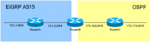
Figure 48: EIGRP and OSPF routing domains
High availability
There are two methods a LAN host can determine its default gateway or first-hop router. The first method uses a dynamic process such as a dynamic routing protocol like RIP (Routing Information Protocol). The main drawback of dynamic discovery protocols is that they require some configuration and processing on the host, which must participate in the dynamic process. The alternative to using a dynamic discovery protocol is to statically configure a default gateway on the host. The static approach simplifies host configuration but also creates a single point of failure. A host configured with a static default gateway is isolated if the gateway fails. It cannot switch to an alternate gateway even if one exists until an administrator manually re-configures the default gateway on the host.
First Hop Redundancy Protocols
There exists a class of redundancy protocols known as FHRPs (First Hop Redundancy Protocols) that include VRRP (Virtual Router Redundancy Protocol), HSRP (Hot Standby Router Protocol), and GLBP (Gateway Load Balancing Protocol). These protocols protect against a single point of failure for the default gateway and may also provide load balancing if multiple uplinks are available at first-hop routers.
Both HSRP and VRRP enable two or more routers on a LAN to work together in a group, sharing a single group IP address. The group IP address is configured as the default gateway in each host. In an HSRP or VRRP group, one router is elected to handle all requests sent to the group IP address. It is called the active router with HSRP and the master router with VRRP. There is at least one standby router with HSRP and similarly at least one backup router with VRRP.
GLPB goes a step beyond VRRP and HSRP by providing load balancing in addition to redundancy.
Virtual Router Redundancy Protocol
VRRP (Virtual Router Redundancy Protocol) enables a group of routers on a LAN segment to form a single virtual router that is also known as a VRRP group. The virtual router is made up of a single router acting as virtual router master and multiple routers acting as virtual router backup. The virtual IP address of the virtual router is then configured on LAN clients as their default gateway.
VRRP Operation
VRRP router priority determines the role that each VRRP router plays. If the IP address of the physical interface on a VRRP router is configured as the virtual IP address, this router will function as the virtual router master. The same priority also determines the likelihood of a router becoming the virtual router master if the virtual router master fails. If there are multiple routers acting as virtual router backup, the one with the highest priority becomes the virtual router master if the original virtual router master fails. You can configure the priority of each virtual router backup with a value of 1 through 254 using vrrp priority command.
VRRP router preemption allows a virtual router backup with a higher priority that comes up to take over the virtual router backup that was elected to become the virtual router master. This preemption is enabled by default so you don’t have to configure anything to make preemption work. If preemption is disabled, the virtual router backup that is elected to become virtual router master remains the master until the original virtual router master comes back online and becomes master again. You may disable preemption by using the no vrrp preempt command interface configuration mode.
A virtual router master sends VRRP advertisements to other routers in the same VRRP group. The advertisements contain the priority and the state of the virtual router master. These advertisements are sent, every second by default, as multicasts to the standard multicast address 224.0.0.18 encapsulated in IPv4 packets.
HSRP (Hot Standby Router Protocol) is a Cisco proprietary FHRP (first-hop redundancy protocol) that is available in two versions. The newer version 2 improves upon version 1 and is now the preferred choice. These two versions of HSRP are not compatible with each other.
HSRP Operation
Two or more routers on a LAN segment form an HSRP group also known as standby group. One router in the group assumes the role of the active router and handles all requests from clients. The other router or routers become standby and take over if the active router fails. The multicast address 224.0.0.102 is used to send HSRP version 2 hello messages. These messages communicate HSRP parameters to other members of the group and also serve as a keep alive.
The problem with HSRP really is that only one router is active at one time. The other routers in the standby group are just sitting there watching the show, until the active router fails. This scheme of things is not very efficient as if you have redundant uplinks connected to the standby routers, all the additional bandwidth provided by these uplinks will not be used.
Gateway Load Balancing Protocol
GLBP (Gateway Load Balancing Protocol) prevents a single point of failure, like HSRP and VRRP, but also allows load-sharing among a group of redundant routers. Multiple first-hop routers on the LAN form a group to offer a single virtual router, also sharing the IP packet forwarding load.
HSRP and VRRP also allow multiple routers to form a virtual router group with a virtual IP address. But only one member of the group is elected as the active router that forwards packets sent to the virtual IP address for the group. The other routers in the group stay idle until the active router fails. In other words, the bandwidth of standby routers is not utilized and goes waste. Although it is possible to configure multiple virtual router groups to achieve load balancing in case of HSRP and VRRP, but it requires configuring different default gateways on different hosts, which is an extra administrative burden.
The advantage of GLBP is that it provides load balancing in addition to redundancy without requiring configuration of different default gateways on different clients.
GLBP Operation
The routers participating in GLBS communicate with each other through hello messages sent every 3 seconds to the multicast address 224.0.0.102, UDP port 3222 (both source and destination). GLBP supports up to 1024 GLBP groups on each physical interface, and up to four active virtual forwarders per group.
Routers participating in GLBP form a group and elect one router as the AVG (active virtual gateway) for that group. Other members of the group provide backup for the AVG if it goes down. The AVG controls all members of the group by assigning a virtual MAC address to each member. Each router takes responsibility of forwarding packets sent to the virtual MAC address assigned to it by the AVG. These routers are each called AVF (active virtual forwarder) for their virtual MAC address. The AVG also responds to ARP (Address Resolution Protocol) requests for the virtual IP address. This is the key to GLBP operation as load balancing is actually achieved by the AVG replying to ARP requests from different hosts with different virtual MAC addresses.
When a client sends an ARP message for the IP address of its default gateway, the AVG responds with the virtual MAC address of one of the AVFs. When another client sends an ARP message for default gateway address resolution, the AVG returns the virtual MAC address of the next AVF. So each client gets a different virtual MAC address for the same virtual IP address of the default gateway. As a result, each client will send its traffic to separate routers despite the fact that they are configured with the same default gateway.
Route aggregation
Route aggregation is an alternate term for route summarization, which is a method used to minimize the number of routing tables required in an IP network.
To implement route summarization in IP Version 4 (IPv4), Classless Inter-Domain Routing (CIDR) must be used. All IP addresses in the route advertisement must share identical high-order bits. The length of the prefix must not exceed 32 bits.
Route summarization offers several important advantages over flat routing. Route summarization can minimize the latency in a complex network, especially when many routers are involved. Because of the reduced number of routing entries, the overhead for routing protocols is minimized. Network stability can be improved by reducing or eliminating unnecessary routing updates after part of the network undergoes a change in topology. Route summarization also greatly reduces processor workloads, memory requirements and bandwidth demand.
Routing metrics
Following are a number of metrics related to routing that you should know for the exam:
- Hop counts are the number of hops necessary to reach a node. A hop count of infinity means the route is unreachable.
- The Maximum Transmission Unit (MTU) defines the largest data unit that can be passed without fragmentation.
- Bandwidth specifies the maximum packet size permitted for Internet transmission.
- Costs are the numbers associated with traveling from point A to point B (often hops). The lower the total costs (the less links in the route), the more that route should be favored.
- Latency is the amount of time it takes for a packet to travel from one location to another.
Recent Comments