N10-007 Install and configure wireless LAN infrastructure and implement the appropriate technologies in support of wireless capable devices
Small office/home office wireless router
A small office/home office (SOHO) network is typically defined as one that serves 1 to 10 users; although, no hard and fast rule exists for this. The commonality between all implementations falling into this category is that usually a small number of users exist, and the physical environment is typically small.
A number of SOHO-labeled solutions are available, including small routers and firewalls. Appropriately, a SOHO router typically serves 1 to 10 users on the system.
Just as when configuring any other type of network, you need to be mindful of your requirements and limitations. The limitations for cable length, device types, environment, equipment, and compatibility do not change just because the network created is smaller.
Today, wireless local area networks (WLANs) provide a flexible and secure data communications system that augments an Ethernet LAN or, in some cases, replaces it. Wireless transmissions send and receive data using radio frequency (RF) signals, freeing you from wired solutions.
In a common wireless implementation, a wireless transceiver (transmitter/receiver), known as an access point, connects to the wired network from a fixed location using standard cabling. The wireless access point receives and then transmits data between the wireless LAN and the wired network infrastructure.
Client systems communicate with a wireless access point using wireless LAN adapters. Such adapters are built into or can be added to laptops, PDAs, or desktop computers. Wireless LAN adapters provide the communication point between the client system and the airwaves via an antenna.
Wireless access points
A wireless access point (AP) is both a transmitter and receiver (transceiver) device used for wireless LAN (WLAN) radio signals. An AP typically is a separate network device with a built-in antenna, transmitter, and adapter. APs use the wireless infrastructure network mode to provide a connection point between WLANs and a wired Ethernet LAN. APs also typically have several ports, giving you a way to expand the network to support additional clients.
Depending on the size of the network, one or more APs might be required. Additional APs are used to allow access to more wireless clients and to expand the range of the wireless network. Each AP is limited by a transmission range—the distance a client can be from an AP and still get a usable signal. The actual distance depends on the wireless standard being used and the obstructions and environmental conditions between the client and the AP.
Roaming
IN SSID broadcast, wireless access points typically broadcast the SSID name into the air at regular intervals. This feature is intended to allow clients to easily discover the network and roam between WLANs. The problem with SSID broadcasting is that it makes it a little easier to get around security. SSIDs are not encrypted or protected in any way. Anyone can snoop and get a look at the SSID and attempt to join the network.
Wireless controllers
A wireless controller is a centralized Wi-Fi management device that manages all the access points in a campus. The following points illustrate why a controller is inevitable for larger networks.
Centralized Authentication: No more individual MAC address tables and updation in each access point, controller provides for a centralized authentication mechanism through individual user name-password based Radius Server/ Active Directory/ LDAP Integration, centralized MAC address filtering or certificate/ shared key based authentication for all the clients from a central location.
VLAN pooling
Whenever a wireless client connects to a wireless network (WLAN), the client is placed in a VLAN that is associated with the WLAN. In a large venue such as an auditorium, a stadium, or a conference where there may be numerous wireless clients, having only a single WLAN to accommodate many clients might be a challenge.
The VLAN select feature enables you to use a single WLAN that can support multiple VLANs. Clients can get assigned to one of the configured VLANs. This feature enables you to map a WLAN to a single or multiple interface VLANs using interface groups. Wireless clients that associate to the WLAN get an IP address from a pool of subnets identified by the interfaces. The IP address is derived by an algorithm based on the MAC address of the wireless client. This feature also extends the current AP group architecture where AP groups can override an interface or interface group to which the WLAN is mapped to, with multiple interfaces using the interface groups. This feature also provides the solution to auto anchor restrictions where a wireless guest user on a foreign location can get an IP address from multiple subnets based on their foreign locations or foreign controllers from the same anchor controller.
When a client roams from one controller to another, the foreign controller sends the VLAN information as part of the mobility announce message. Based on the VLAN information received, the anchor decides whether the tunnel should be created between the anchor controller and the foreign controller. If the same VLAN is available on the foreign controller, the client context is completely deleted from the anchor and the foreign controller becomes the new anchor controller for the client.
If an interface (int-1) in a subnet is untagged in one controller (Vlan ID 0) and the interface (int-2) in the same subnet is tagged to another controller (Vlan ID 1), then with the VLAN select, client joining the first controller over this interface may not undergo an L2 roam while it moves to the second controller. Hence, for L2 roaming to happen between two controllers with VLAN select, all the interfaces in the same subnet should be either tagged or untagged.
As part of the VLAN select feature, the mobility announce message carries an additional vendor payload that contains the list of VLAN interfaces in an interface group mapped to a foreign controller’s WLAN. This VLAN list enables the anchor to differentiate from a local to local or local to foreign handoff.
LWAPP
LWAPP is Cisco’s proprietary protocol used to provide central control of Access Points. With LWAPP, the AP automatically detects the best available Cisco Wireless LAN Controller (WLC) to download appropriate policies and radio and SSID configuration information with no hands-on intervention.
Normally a switch that receives frames from a wireless client A (via an AP) would forward the frm to the destination client B. In the LWAPP scenario though we need this frame to go first to the controller. In order for this to happen LWAPP adds extra headers to the frame. In Layer 2 mode LWAPP uses a layer 2 header IF the controller is in the same LAN so that the AP does not need an IP address. The controller could be in the same LAN or a different LAN. The layer 3 header contains the destination IP address of the controller, the source MAC of the AP and the destination MAC of the router.
Wireless bridge
Bridges are used to divide larger networks into smaller sections. Bridges accomplish this by sitting between two physical network segments and managing the flow of data between the two. By looking at the MAC address of the devices connected to each segment, bridges can elect to forward the data (if they believe that the destination address is on another interface) or block it from crossing (if they can verify that it is on the interface from which it came). Figure 57 shows how a bridge can be used to segregate a network.
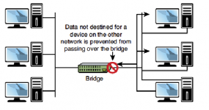
Figure 57: Bridge is used to segregate a network
An AP can operate as a bridge connecting a standard wired network to wireless devices or as a router passing data transmissions from one access point to another.
Site surveys
There are three types of surveys: Passive, Active, and Predictive.
Passive Survey
Passive surveys are surveys that are performed with a listen-only mode. The survey client never associates to the access point (AP). Such surveys can be helpful when you look for rogue devices or you want a good gauge of downlink RF coverage from the infrastructure devices.
These can be accomplished with a passive survey:
- Identify rogues
- Locate RF trouble zones quickly
- Validate final RF setting
- Perform initial surveys
The most significant loss of information with passive surveys is uplink information, Physical (PHY) rate boundaries and retransmission. PHY rates are generally based on RF signal and noise levels. A passive survey only reports signal propagation for beacons measured by particular clients. PHY rates can only be measured by actual data that is sent to and from an AP.
Active Survey
Active surveys are performed with the survey client associated to the APs used throughout the survey. When a client is associated, it performs all the tasks a typical 802.11 client performs, which includes rate shifting data rates as the RF condition changes and performs retransmissions. Active surveys are commonly used for new WLAN deployments because they provide the most details upon which to base a design.
There are two main methods used in active surveys:
- Basic Service Set Identifier (BSSID) Method: This method locks a client into an AP’s radio MAC address and prevents the client from roaming.
- Service Set Identifier (SSID) Method: This is more commonly used for post-deployment scenarios and used to survey multiple APs. It enables the survey client to associate to an SSID where the client roams between multiple APs.
Predictive Surveys
Predictive surveys are performed with a software program. The program uses the information about the coverage area to perform AP placements based on RF algorithms. These surveys are typically void of any type of field measurements.
The best times to incorporate a predictive survey include:
- When the deployment environment has not yet been built.
- In order to obtain a budgetary environment for WLAN-related hardware.
- When roaming requirements are less stringent.
Checklist of Base Items to ask the Site Survey Provider
- Frequency bands to be used: 2.4 GHz, 5 GHz.
- Tools to be used in order to complete the survey, such as Airmagnet, Ekahau, and so on.
- Active or passive survey.
- Auto sampling.
- Type of adapter to be used to perform the survey.
- The coverage areas that are ‘in-scope’ or ‘out-of-scope’, such as stairwells, elevators, electric rooms, air shafts, mechanical areas, and so on.
- Heat map that displays RF coverage for all ‘in-scope’ areas with coverage set at the target RSSI for cell edge with a signal legend.
- Heat map that displays SNR for all ‘in-scope’ areas with the target SNR and an SNR legend.
- Heat map that displays the noise floor for all ‘in-scope’ areas with the target noise floor set and a noise floor legend.
- Spectrum Analysis screenshots and recordings of possible sources of interference. Define what is desired in the analysis – Fast Fourier Transform (FFT), spectrograms, duty cycle, max hold, and so on.
- Identify and list possible sources of interference. A walkthrough should be performed through the facility. Ask about and look for possible sources of interference, such as microwave ovens, cordless phones, and so on.
- The AP hardware to be used. For example, the heat maps may look different for Aironet 3500 Series Access Points verses Aireonet 3600 Series Access Points. The AP should be selected to match the AP that is planned to be purchased and deployed.
- If a passive survey is performed, define how many AP’s at a time are planned to be used, one or three. Three is quicker than one, but the AP placements might be sub-optimal.
- Identify the type of survey to be conducted: voice, location, or data only.
Frequencies
There are many wireless networking specifications that exist under the umbrella, 802.11. These standards though implemented in the same way have different characteristics in terms of speed, transmission ranges and others. The main standards to be considered are:
– IEEE 802.11: This is the initial wireless standard. Two variations of the standard were implemented. In terms of transmission speeds and the radio frequency, the systems were identical, the difference was in the way data traveled through the RF media. FHSS (Frequency Hopping Spread Spectrum) was used by one and DSSS (Direct Sequence Spread Spectrum) by the other. Modern networks which are always challenging networks for speed displaced them soon. The characteristics of 802.11 are:
| Frequency /Media | 2.4GHz RF |
| Speed | 1 to 2 Mbps |
| Topology | Ad hoc/Infrastructure |
| Transmission Range | 20 feet indoors |
| Access Method | CSMA/CA |
– IEEE 802.11a: When it comes to rate of transfer of data, this standard has left the 802.11 standards much behind. The shortcoming of this system is that it not compatible with other wireless standards 802.11b and 802.11g. The characteristics of 802.11a are:
| Frequency /Media | 5 GHz RF |
| Speed | Up to 54 Mbps |
| Topology | Ad hoc/Infrastructure |
| Transmission Range | 25 to 75 feet indoors; building materials can affect the range |
| Access Method | CSMA/CA |
– IEEE 802.11b: This is compatible with 802.11g and devices with earlier standards. It provides for a maximum transmission data rate of 11Mbps. The characteristics of 802.11b are:
| Frequency /Media | 2.4GHz RF |
| Speed | Up to 11 Mbps |
| Topology | Ad hoc/Infrastructure |
| Transmission Range | Up to 150 meters indoors; the range can be influenced by the building materials that have been used. |
| Access Method | CSMA/CA |
– IEEE 802.11g: It is one of the most popular wireless standard adhered to these days. It is compatible with 802.11b. The characteristics of 802.11g are:
| Frequency /Media | 2.4 GHz RF |
| Speed | Up to 54 Mbps |
| Topology | Ad hoc/Infrastructure |
| Transmission Range | Up to 150 feet indoors; building materials can affect the range |
| Access Method | CSMA/CA |
– IEEE 802.11n: It is the most recent to be added to the league of standards pertaining to wireless networking. It concentrates on throughput. The base is taken to be 100 Mbps and with the right conditions, it is expected to reach a level of 600 Mbps. The characteristics of 802.11n are:
| Frequency /Media | 2.4GHZ/5 GHz RF |
| Speed | Up to 600 Mbps |
| Topology | Ad hoc/Infrastructure |
| Transmission Range | 175+ feet indoors; building materials can affect the range |
| Access Method | CSMA/CA |
802.11n is directed towards bringing major changes in the wireless networking environment. It holds promises of greater speeds and distance. It uses a mixture of all the standards of 802.11 to enhance wireless networking to the next level. The technologies that have played an important role are:
- MIMO: It uses the technology Multiple Input Multiple Output (MIMO) which is considered as the best technology for 802.11n. MIMO uses the technique of multiplexing which raises its speed and the range that a network can cover. Multiple signals are combined and transmitted over a single line or media.
- Channel Bonding: The next factor that has played an important role is Channel Bonding. This allows channels to bond allowing for data rate to be nearly doubled. 802.11b and 802.11g standards use single channels and when channel bonding is incorporated, using two channels at one point of time becomes possible and hence transmission rates are increased.
Channels
There are a couple of wireless channels that provide radio frequency. The frequency band is available under 802.11a who provides more channels and data throughput.
– Radio Frequency: RF or Radio Frequency is an important part of wireless communications. It is the RF band that is used for communication. As already mentioned the standards prescribe the RF ranges that can be used with each standard.
– Radio Channels: With respect to the channels, a wide frequency band is available under 802.11a allowing more channels and more data throughput. The standard 802.11a can support up to 8 non-overlapping channels, whereas 802.11b and 802.11g can only support up to three channels as the bandwidth used is much smaller. Non-overlapping channels are the prescribed ones for communication. Overlapping channels cannot be ignored while troubleshooting a wireless network.
– Spread Spectrum Technology: The manner in which data signals travel through a radio frequency is termed as spread spectrum. Data is transmitted using the narrowband transmission. It is a requisite of spread spectrum that data signals change their data pattern or alternate between frequencies. Spread spectrum compromises on bandwidth efficiency for attaining more reliable and secure transmission. There are three types of spread spectrum technologies:
- Frequency-Hopping Spread Spectrum (FHSS) Technology: In FHSS, narrowband signals are used. These signals change frequencies in a predictable pattern. Hopping of data signals between narrow channels is known as Frequency hopping. FHSS is a strong technology when it comes to dealing with interferences. It is best suited for networks covering large areas. Directional antennas cannot be used for reducing the effect of environment. It is not a technology in vogue.
- Direct-Sequence Spread Spectrum (DSSS) Technology: Using this technology, the signal is spread over full transmission frequency spectrum. With every bit of data, a 32 pattern bit called the chip is also sent. This is done for the purposes of security as well as to ensure delivery. It is considered a safe technology as multiple redundant copies are sent. It is immune to interference and noise, but deeply effected by environmental factors.
- Orthogonal Frequency Division Multiplexing: It is a transmission technique, used for transferring large amounts of data. The data is transmitted over frequencies, which are separate and evenly placed. The radio signal is split into separate frequencies by this technology and a simultaneous transmission is made to the receiver. Cross Talk is reduced by the use of this technology as the signal is split and transferred over multiple frequencies.
Goodput
In networking terms – for wired and wireless networks – goodput is used to describe the number of packets that are exchanged between the applications that use the network.
A more commonly known related term is throughput. It measures the amount of packets exchanged over the network to determine network efficiency. Goodput can also be described as measuring the throughput at the application level.
Antenna placement
Ideally, you locate the AP as close as possible to the antennas. The farther the signal has to travel across the cabling between the AP and the antenna, the more signal reduction (also known as RF attenuation) you experience. For instance, if you are locating an antenna in a courtyard to service clients roaming outside, don’t place the AP in a closet, dozens of feet away from the antenna. Instead, place the AP outside in a weatherproof enclosure, so it’s closer to the antenna. An even better idea is to use a 1300 series, which is weatherproof.
Signal loss depends on what type of cable you use. Cisco offers two types of cable. One is similar to LMR400 and has a loss of 6.7dB per 100 feet, whereas the other is similar to LMR600 with 4.4dB per 100 feet. For every 3dB, you lose about half the signal’s power. This loss occurs on both transmission and reception. You can use higher-quality cable to reduce signal loss over longer cables, but keep in mind that higher-quality cable is more expensive.
In addition, if you use an 802.11a product, cable loss is an even more significant issue. Loss increases with frequency, and coaxial cable has even more attenuation with 5-GHz signals than 2.4-GHz signals.
Antenna types
It is important to understand the coverage used by an antenna before selecting the type of an antenna to be used. The wireless environment controls the choice of the antenna. Typically, antennas are:
- Omnidirectional: It is useful where wave degrees are to be dispersed in 360-degree pattern. It is best suited where coverage is required in all directions. These antennas are used when broad based signals are required. It allows access from multiple locations. The disadvantage with this type of antenna is the signal is not very strong and hence remains limited to smaller distances. Omnidirectional antennas are preferred for home and small offices.
- Directional: These antennas are used when signal is to be concentrated in one particular direction. It transmits a focused signal, meaning a greater distance can be traveled with stronger signals between two points. These are best suited for point to point configurations; as they travel greater distance. These are preferred when transmission needs to be tunneled through a series of obstacles. A chartered path helps to concentrate and strengthen the signal. The figure given below illustrates both directional as well as omnidirectional antennas.
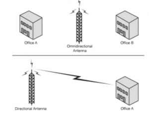
Figure 58: Directional Antenna Signal
MIMO/MUMIMO
802.11n takes the best from the 802.11 standards and mixes in some new features to take wireless to the next level. First among these new technologies is multiple inputs multiple output (MIMO) antenna technology.
MIMO is unquestionably the biggest development for 802.11n and the key to the new speeds. Essentially, MIMO uses multiplexing to increase the range and speed of wireless networking. Multiplexing is a technique that combines multiple signals for transmission over a single line or medium. MIMO enables the transmission of multiple data streams traveling on different antennas in the same channel at the same time. A receiver reconstructs the streams, which have multiple antennas as well. By using multiple paths, MIMO provides a significant capacity gain over conventional single-antenna systems, along with more reliable communication.
In addition to all these improvements, 802.11n enables channel bonding that essentially doubles the data rate again. What is channel bonding? The 802.11b and 802.11g wireless standards use a single channel to send and receive information. With channel bonding, you can use two channels at the same time. As you might guess, the ability to use two channels at once increases performance. It is expected that bonding can help increase wireless transmission rates from the 54Mbps offered with the 802.11g standards to a theoretical maximum of 600Mbps. 802.11n uses the OFDM transmission strategy.
Signal strength
AP signal strength is related to coverage and types of antennas.
Coverage defines the ability of wireless clients to connect to a wireless AP with a signal strength and quality high enough to overcome the effects of RF interference. The edge of the coverage for an AP is based on the signal strength and SNR measured as the client device moves away from the AP.
The signal strength required for good coverage varies dependent on the specific type of client devices and applications on the network.
The minimum recommended wireless signal strength for voice applications is -67 dBm and the minimum SNR is 25 dB.
The first step in the analysis of a post site survey is to verify the ‘Signal Coverage’. The signal coverage is measured in dBm. You can adjust the color-coded signal gauge to your minimum-allowed signal level to view areas where there are sufficient and insufficient coverage. The example in Figure 59 shows blue, green, and yellow areas in the map have signal coverage at -67 dBm or better. The areas in grey on the coverage maps have deficient coverage.
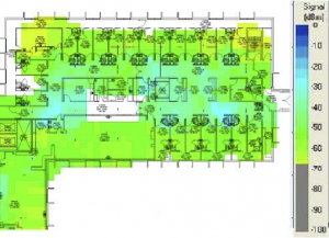
Figure 59: signal at -67dBm
SSID broadcast
In their default configuration, wireless access points typically broadcast the SSID name into the air at regular intervals. This feature is intended to allow clients to easily discover the network and roam between WLANs. The problem with SSID broadcasting is that it makes it a little easier to get around security. SSIDs are not encrypted or protected in any way. Anyone can snoop and get a look at the SSID and attempt to join the network.
Topologies
A topology refers to a network’s physical and logical layout. A network’s physical topology refers to the actual layout of the computer cables and other network devices. A network’s logical topology refers to the way in which the network appears to the devices that use it.
Several topologies are in use on networks today. Some of the more common topologies are the bus, ring, star, mesh, and wireless. The following sections provide an overview of each.
Adhoc
In a wireless ad hoc topology, devices communicate directly between themselves without using an access point. This peer-to-peer network design is commonly used to connect a small number of computers or wireless devices. For example, an ad hoc wireless network may be set up temporarily between laptops in a boardroom or to connect systems in a home instead of using a wired solution. The ad hoc wireless design provides a quick method to share files and resources between a small number of systems. Figure 60 shows an ad hoc wireless network.
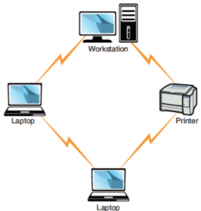
FIGURE 60: Ad hoc wireless topology.
Mesh
A mesh topology offers high redundancy by providing several paths for data to reach its destination. In a true mesh network, each device on the network is connected to every other device, so if one cable fails, another can provide an alternative data path. Although a mesh topology is resilient to failure, the number of connections involved can make a mesh network somewhat tricky to troubleshoot. When troubleshooting a mesh network, consider the following points:
- A mesh topology interconnects all devices on the network, offering the highest level of redundancy of all the topologies. In a pure mesh environment, all devices are directly connected to all other devices. In a hybrid mesh environment, some devices are connected only to certain others in the topology.
- Although a mesh topology can accommodate failed links, mechanisms should still be in place so that failed links are detected and reported.
- Design and implementation of a true mesh network can be complex and often requires specialized hardware devices.
Mesh networks are so rare that it’s unlikely you will be faced with troubleshooting one, but there will likely be questions on the Network+ Exam that focus on mesh networks.
Infrastructure
This form of the network is used to extend a wired LAN to include wired devices in it. Communication between the wireless devices and the wired LAN takes place through a base station that is AP (access point). The AP acts as a bridge between a wireless and wired LAN. APs need to stay connected to the wired network and are not mobile; hence they end up becoming a part of the wired network. There may be several access points or a single access point influencing the extent of the area that is covered.
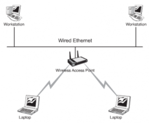
Figure 61: An Infrastructure Wireless Topology
Mobile devices
Wireless Internet access is provided by a Wireless Internet Service Provider (WISP). The WISP provides public wireless Internet access known as hotspots . Hotspots offer Internet access for mobile network devices such as laptops, handheld computers, and cell phones in airports, coffee shops, conference rooms, and so on. A hotspot is created using one or many wireless access points near the hotspot location.
- Client systems might need to install special application software for billing and security purposes; others require no configuration other than obtaining the network name (Service Set Identifier [SSID]). Hotspots do not always require a fee for service because companies use them as a marketing tool to lure Internet users to their businesses. Hotspots are not everywhere, but finding them is not difficult. Typically, airports, hotels, and coffee shops advertise that they offer Internet access for customers or clients. In addition, WISPs list their hotspot sites online so that they are easily found.
- Establishing a connection to a wireless hotspot is a straightforward process. If not equipped with built-in wireless capability, laptops require an external wireless adapter card. With the physical requirements of the wireless card taken care of, connect as follows:
- When you arrive at the hotspot site, power up your laptop. In some instances, you might need to reboot your system if it were on standby to clear out old configuration settings.
- The card might automatically detect the network. If this is the case, configuration settings, such as the SSID, are automatically detected, and the wireless Internet is available. If Internet access is free, there is little else to do; if it is a paid-for service, you need to enter a method of payment. One thing to remember is to verify that you use encryption for secure data transfer.
- If for some reason the wireless settings are not automatically detected, you need to open your wireless NIC’s configuration utility and manually set the configurations. These settings can include setting the mode to infrastructure, inputting the correct SSID, and setting the level of encryption used.
In addition to using a WISP, some companies such as hotels and cafes provide wireless Internet access by connecting a wireless router to a DSL or cable Internet connection. The router becomes the wireless access point to which the users connect, and it enables clients to connect to the Internet through the broadband connection. The technology is based on the 802.11 standards, typically 802.11b/g/n, and client systems require only an internal or external wireless adapter.
Recent Comments