N10-007 Install and properly terminate various cable types and connectors using appropriate tools
Copper connectors
All forms of network media need to be physically attached to the networked devices in some way. Media connectors provide the interface between the cables and the devices to which they attach (similar to the way an electrical cord connects a television and an electrical outlet).
RJ Connectors: The RJ-45 is the most commonly used connector in the modern networks. These are quite similar to the RJ-11 connectors used in telephone connections. The RJ-11 connector supports only six wires whereas RJ-45 connector supports eight wires. The figure given below illustrates a RJ-11 connector.

Figure 15: RJ-11 Connectors
F-Type Connectors and RG-59/RG-6 Cables: The F type connectors are used for connecting coaxial cable (RG-59 and RG-6) to devices. These are most commonly used for connecting internet modems to cable or satellite internet provider equipment and for peripheral devices. These are screwed in by hand to ensure a firm contact between the cable and the device. The figure given below illustrates an F-Type Connector.
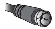
Figure 16: F-Type Connector
RS-232 Standard: The full form of this connector is Recommended Standard 232. It is a TIA/EIA standard for serial transmission. It helps connect computers and peripheral devices such as modems, mice, and keyboards. These were introduced in the sixties and are still prevalent today. The connector has been upgraded from time to time and the third version is being used today. This type has a limit of about 50 feet and transfer rate of about 20kbps. It uses a 25 pin or a 9 pin connector. The figures given below illustrate the connectors.
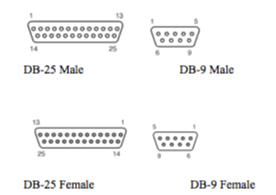
Figure 17: RS-232 DB Connectors
Fiber Connectors: There are multiple types of connectors that are associated with fiber optic cable. The figures given below illustrate different type of fiber connectors. The type of connector to be used is determined by the implementation.

Figure 18: Fiber Connectors
IEEE 1394: This is also known as FireWire and is used for connecting peripheral devices to the network. It also allows for creation of smaller networks. There are two versions available – a four pin or a six-pin version. The figure given below illustrates both.
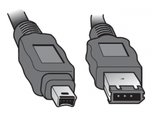
Figure 19: IEEE 1394
(FireWire) Connectors
Universal Serial Bus (USB): USB ports are commonly used these days and can be found on both desktops as well as laptops. These are used to connect peripheral devices such as MP3 players, digital cameras with the network. Wireless Network cards can also be used as plug-ins into the USB port. The number of ports on a system varies from two to four. Hubs can also be used for additional ports. The figure below illustrates Type A and Type B ports the most common ones used these days.
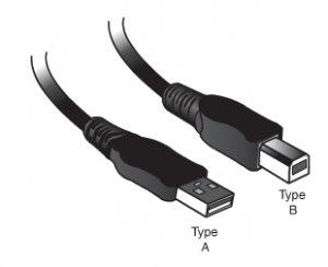
Figure 20: USB Connectors
Twisted-Pair Cabling
Twisted-pair cabling has been around for a long time. It was originally created for voice transmissions and has been widely used for telephone communication.
Today, in addition to telephone communication, twisted pair is the most widely used medium for networking.
The popularity of twisted pair can be attributed to the fact that it is lighter, more flexible, and easier to install than coaxial or fiber-optic cable. It is also cheaper than other media alternatives and can achieve greater speeds than its coaxial competition. These factors make twisted pair the ideal solution for most network environments.
Two main types of twisted-pair cabling are in use today: Unshielded Twisted Pair (UTP) and Shielded Twisted Pair (STP). UTP is significantly more common than STP and is used for most networks. Shielded twisted pair is used in environments in which greater resistance to EMI and attenuation is required.
The greater resistance comes at a price, however. The additional shielding, plus the need to ground that shield (which requires special connectors), can significantly add to the cost of a cable installation of STP.
STP provides the extra shielding by using an insulating material that is wrapped around the wires within the cable. This extra protection increases the distances that data signals can travel over STP but also increases the cost of the cabling. Figure 21 shows UTP and STP cabling.
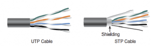
Figure 21: UTP and STP cabling
BNC Connectors
BNC connectors are associated with coaxial media and 10Base2 networks. BNC connectors are not as common as they previously were, but they still are used on some networks, older network cards, and older hubs. Common BNC connectors include a barrel connector, T-connector, and terminators. Figure 22 shows two terminators (top and bottom) and two T-connectors (left and right).
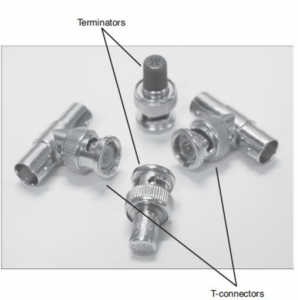
Figure 22 – BNC connectors
110 Blocks (T568A, T568B)
Two main types of punchdown blocks are used: type 66 and type 110. Type 66 is an older design used to connect wiring for telephone systems and other low-speed network systems and is not as widely used as type 110. The 66 block has 50 rows of IDC contacts to accommodate 25-pair twisted-pair cable.
Block 66 was used primarily for voice communication. Although it is approved for Category 5, it may not be suitable due to crosstalk problems. In the network wiring closet, the 110 block is used to connect network cable to patch panels. 110 connections can also be used at the other end of the network cable at the RJ-45 wall jack. 110 blocks are preferred over the older 66 blocks, the 110 block improves on the 66 block by supporting higher frequencies and less crosstalk. Therefore, it supports higher-speed networks and higher grade twisted-pair cable. The termination will be T568A or T568B, depending upon which wiring standard is used, and both were illustrated in Figure 23.
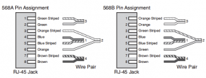
Figure 23 – Pin assignments for the T568A and T568B standards
Copper cables
Shielded vs unshielded
The environment determines whether cable should be shielded or unshielded. Quiet office environments, busy retail establishments, and individual workshops all require different levels of shielding.
Shielding
Shielding is the protective sheath surrounding and protecting the wires of the cable from electromagnetic leakage and interference. This electromagnetic (EMI) activity is commonly referred to as noise. Sources of EMI in the workplace include lift motors, fluorescent lights, generators, compressors, air conditioners, and photocopiers.
Foil-shielded and Copper-shielded
To protect your data in a noisy area (with high EMI), choose a shielded cable. Foil is the most basic cable shield, but a copper-braid shield provides more protection. Use a foil-shielded cable in busy office or retail environments. For industrial environments, you may want to choose a copper-braid shield. For quiet office environments, choose unshielded cable.
Plastic and Metal Hoods
Hoods (the protective enclosure housing the connectors and covering the pinning) are either metal or plastic. Metal hoods offer protection against electromagnetic interference (EMI) and radio-frequency interference (RFI) at the termination point on the connector shell.
Generally, you should choose metal hoods when using shielded cable and plastic hoods with unshielded cable.
CAT3
The Category 3 or CAT3 standard was used heavily in the early 90′s for wiring offices and homes. It’s still used in two-line phone configurations, but has largely fallen out of favor for wired networking thanks to the Category 5e cable’s superior performance. CAT3 can be relied on to handle data speeds of up to 10 Mbps, but no more. Its maximum frequency clocks in at 16 MHz. Like many other cabling options, it relies on copper for data and power transmission. While theoretically limited to 10BASE-T Ethernet, it can actually support 100BASE-T4 speeds by using 4 wires instead of 2 to achieve 100 Mbps throughput.
CAT5
Around 2000 or so, CAT5 overtook CAT3 as the Ethernet cable of choice for LAN networking. CAT5 uses either the 10BASE-T or 100BASE-T standard for data transmission. Using two cable pairs to signal over copper wire, CAT5 is now largely archaic and isn’t widely used for Ethernet connections. It’s rated for a maximum frequency of 100 MHz and top speeds of 100 Mbps. CAT5 uses 8P8C modular connectors to connect devices together, and can be used effectively at lengths of up to 100 meters. Today, CAT5 cable has been replaced for the most part by CAT5e.
CAT5e
While very similar to CAT5 in appearance, CAT5e introduces some new wrinkles in the equation. For one thing, CAT5e uses four pairs of copper wire rather than the two that CAT5 relies on. In addition, the wire pairs are twisted more tightly and are sheathed in heavy-duty shielding to eliminate crosstalk. Crosstalk cuts down on the speed at which a cable can transmit information. Thanks to its internal upgrades, CAT5e is capable of achieving 1000BASE-T speeds. In other words, it can handle up to 1 Gbps of throughput at a distance of up to 100 meters. As of today, it’s the most common type of cabling found in modern homes and offices for Ethernet purposes.
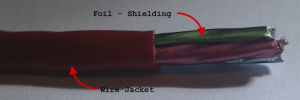
Figure 24: CAT5e Cable foil shielding
CAT6
For back-end, high-capacity networking, CAT6 supports Gigabit Ethernet needs. Supporting frequencies of up to 250 MHz and the 10BASE-T, 100BASE-TX, 1000BASE-T, and 10GBASE-T standards, it can handle up to 10 Gbps in terms of throughput. Thanks to better cable insulation, CAT6 reduces potential crosstalk even more so than CAT5e. When used for Gigabit Ethernet and below, the maximum allowable cable length is 100 meters. For 10GBASE-T speeds, the maximum cable length is 55 meters. The one major caveat of CAT6 cables is that installation can be tricky, as compatibility with 8P8C requires the use of special adapter pieces for optimal performance.
CAT6e or Enhanced CAT6
These are an enhancement on the standard CAT6 cables, as they perform much better when installed in an environment with high noise or RF interference. While better than CAT6, they are not as good as the CAT6a or CAT6 Augmented standard cables.
Straight-through vs crossover vs rollover
Crossover Cable Vs. Straight Cable
Hubs and Switches can be interconnected using either crossover or straight through cable. The difference between the two is that in crossover cable, two sets of wires are crossed and in a straight through cable all the wires run straight through. For example, in a cross over cable wires 1 and 3 are crossed over with wires 2 and 6. Figures 1.23 and 1.24 illustrate the differences between the two cable types.
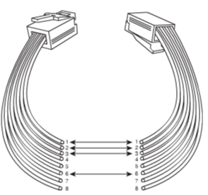
Figure 25: Pin Outs for a Straight through Twisted Pair Cable
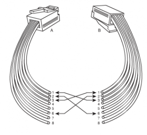
Figure 26: Pin Outs for a Cross over Twisted Pair Cable
Roll over and Loopback Cables
The rollover is proprietary of Cisco and is not usable on any other equipment. It looks like an Ethernet UTP cable and is used to interconnect a computer to a router or a switch console port. It has eight wires and RJ connectors on each end connected to the router and the computer port. As far as the arrangement of the pin outs is concerned, pin 1 on the end of the rollover cable is connected to pin 8 at the other end of the cable; pin 2 with pin 7, pin 3 with pin 6 and so on. The ends are reversed following the same pattern. Once connection is made between the PC and the Cisco terminal, the Cisco equipment is accessible from the computer system. This is made possible by programs such as Hyper Terminal.
Also known as loopback plug, it is used in testing, isolating network problems and trouble shooting. The link light on a device can be made to come in if the set up is made correctly. It is a fast and a cost effective method for checking cabling problems.
The outgoing data is signaled back to the system by using a loopback plug. The system is made to believe that it is sending as well as receiving data. It uses UTP cable and RJ-45 connectors.
Fiber connectors
There are several types of fiber optic connectors available today. The most common are: ST, SC, FC, MT-RJ and LC style connectors.
All of these types of connectors can be used with either multimode or single mode fiber.
There are three types of polishes, which can be applied to a fiber connector: PC or Physical contact, UPC or Ultra Physical contact and APC or Angled Physical contact.
Each polish type exhibits a different level of back reflection. Back reflection is a measure of the light reflected off the end of a fiber connector. This light is measured in decibals.
For certain applications, the amount of back reflection on a fiber connector is critical.
Fiber cables
There are two types of optical fibers available:
- Multimode Fiber (MMF): This type has a larger core than the single mode, allowing hundreds of light rays to pass through. Light rays bounce around in the core moving towards their destination, and as a result their speed slows down, potency is reduced and take longer to travel.
- Single Mode Fiber (SMF): This has a smaller core than the MMF and allows light to pass as a beam of light. It transmission abilities are more than the MMF in terms of speed and distance.
Compositions: The internal composition of fiber cables and the size of core can vary. The common types of fiber-optic cable are:
- 62.5 micron core/125 micron cladding multimode
- 50 micron core/125 micron cladding multimode
- 8.3 micron core/1 25 micron cladding single mode
Media converters
Network technologies change rapidly, and administrators are always on the lookout for cost-effective ways to increase network performance. The demand for higher speeds and greater distances keeps administrators on their toes. The process to incorporate new technology with older infrastructure is made easier with media converters.
Network media converters are used to interconnect different types of cables within an existing network. For example, the media converter can be used to connect newer Gigabit Ethernet technologies with older 100BaseT networks. The ability to combine networks and increase networking flexibility while decreasing the cost of having to retrofit the network to accommodate new technology is important. Converters come in many shapes and sizes to connect to a variety of networks. This includes coax, twisted-pair, single mode, and multimode fiber. Converters can be designed to work with any network type, including Ethernet, Fast Ethernet, Gigabit Ethernet, Asynchronous Transfer Mode (ATM), Fiber Distributed Data Interface (FDDI), and token ring.
When you have two dissimilar types of network media, a media converter is used to allow them to connect. Depending upon the conversion being done, the converter can be a small device barely larger than the connectors themselves, or a large device within a sizable chassis.
Reasons for not using the same media throughout the network, and thus reasons for needing a converter, can range from cost (gradually moving from coax to fiber), disparate segments (connecting the office to the factory), or needing to run a particular media in a setting (the need for fiber to reduceEMI problems in a small part of the building).
Figure 27 shows an example of a media converter. The one shown converts between 10/100/1000TX and 1000LX (with an SC-type connector).
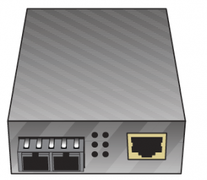
Figure 27: 1000tx to 1000LX media converter
Tools
Cable Testers: Cabling problem often occur while the network installation and shifting. In case the cable is broken it would disconnect the two devices connected by it. Various types of cable broken problems are:
1) Cable might have an open circuit i.e. wires from one end do not connect to the other end of cable.
2) Cable might have short i.e. wires in the cable connect to the other wires
3) There might be a wire map problem i.e. wires in the cable do not connect properly to the jack or plug.
4) There might be a crosstalk i.e. electric signal leaks from one wire to another.
5) A broken cable might have received interference from nearby hardware in form of unwanted signals.
6) Impedance mismatch is also a major factor in broken cables
There are various devices used to rectify the above problems they are:
1) Cable Testers: They check for continuity and wire map problems.
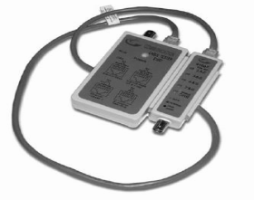
Figure 28: Cable Tester
2) TDRs and OTDRs: These are the devices that locate the area where the cable is broken. TDRs work with the copper cables and OTDRs work with the fibre cable. The only difference between the TDRs and OTDRs is the media rest the working of both is same.
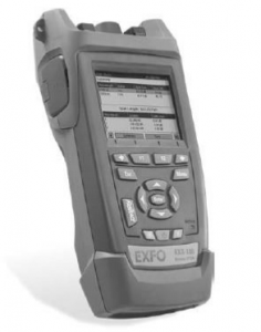
Figure 29: TDR
3) Certifiers: They are used to test the cable for the amount of data that it can send. Certifiers ensure that the cable is handling the amount of data that is given on the cable. In case there in no break in the cable check with the certifiers. Certifiers should be used if there is a slowdown in the network.
4) Voltage Event Recorder: Proper temperature and power needs to be maintained for the devices to work properly. If there is too much heat it might result in network devices failing. We should check devices with voltage event recorder and a temperature monitor.
5) Protocol Analyzers: It monitors various protocols working at different layers of the network. They help in network troubleshooting as they provide the complete information on various layers. For example if we monitor the network and see that there is problem at application layer or network layer we can rectify the problem.
6) Cable Strippers: This is a device used to make cables. Now days cable strippers and punch down come as one device.
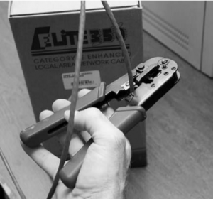
Figure 30: Cable Stripping and Crimping Tool
7) Multimeters: They are used to test voltage, resistance and continuity. This is very important tool to test cable infrastructure. Multimeters are very helpful in checking WAN connections such as ISDN, Lease line etc.
8) Tone Probe and Tone Generators: Tone probes and tone generators collectively help us to locate cables.
9) Butt Sets: They are used to tap into 66 or 110-block to check that if a particular line is working or not.
10) Punchdown Tools: They are used to put wires into 66 or 110-block. Use punchdown tools in case we see that the wires are loosely punched. They are used in case of new installation and for repunching in case of loose wires.
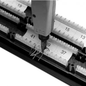
Figure 31: Punch Down Tool
Recent Comments