N10-007 Explain the characteristics and benefits of various WAN technologies
Fiber
Early fiber optic transmission systems put information onto strands of glass through simple pulses of light. A light was flashed on and off to represent the “ones” and “zeros” of digital information. The actual light could be of almost any wavelength (also known as color or frequency) from roughly 670nm to 1550nm.
During the 1980s, fiber optic data communications modems used low-cost LEDs to put near-infrared pulses onto low-cost fiber. As the need for information increased, the need for bandwidth also increased. Early SONET systems used 1310nm lasers to deliver 155 Mb/s data streams over very long distances. But this capacity was quickly exhausted. Advances in optoelectronic components allowed design of systems that simultaneously transmitted multiple wavelengths of light over a single fiber. Multiple high-bit rate data streams of 2.5 Gb/s, 10 Gb/s and, more recently, 40 Gb/s and 100Gb/s could be multiplexed through divisions of several wavelengths. And so was born Wavelength Division Multiplexing (WDM).
- CWDM – Coarse Wavelength Division Multiplexing. WDM systems with fewer than eight active wavelengths per fiber.
- DWDM – Dense Wavelength Division Multiplexing. WDM systems with more than eight active wavelengths per fiber.
Types of WDM
Currently, there are two types of WDM in existence today: Coarse WDM (CWDM) and Dense
WDM (DWDM). Backwards as it may seem, DWDM came well before CWDM, which appeared only after a booming telecommunications market drove prices to affordable lows. Whereas CWDM breaks the spectrum into big chunks, DWDM dices it finely. DWDM fits 40-plus channels into the same frequency range used for two CWDM channels.
CWDM is defined by wavelengths. DWDM is defined in terms of frequencies. DWDM’s tighter wavelength spacing fit more channels onto a single fiber, but cost more to implement and operate.
Distinctive CWDM differences
CWDM can—in principle—match the basic capabilities of DWDM but at lower capacity and lower cost. CWDM enables carriers to respond flexibly to diverse customer needs in metropolitan regions where fiber may be at a premium. However, it’s not really in competition with DWDM as both fulfill distinct roles that largely depend upon carrier-specific circumstances and requirements anyway. The point and purpose of CWDM is short-range communications. It uses wide-range frequencies and spreads wavelengths far apart from each other. Standardized channel spacing permits room for wavelength drift as lasers heat up and cool down during operation. By design, CWDM equipment is compact and cost-effective as compared to DWDM designs.
Distinctive DWDM differences
DWDM is designed for long-haul transmission where wavelengths are packed tightly together. Vendors have found various techniques for cramming 32, 64, or 128 wavelengths into a fiber. When boosted by Erbium Doped-Fiber Amplifiers (EDFAs)—a sort of performance enhancer for high-speed communications—these systems can work over thousands of kilometers. Densely packed channels aren’t without their limitations. First, high-precision filters are required to peel away one specific wavelength without interfering with neighboring wavelengths. Those don’t come cheap. Second, precision lasers must keep channels exactly on target. That nearly always means such lasers must operate at a constant temperature. High-precision, high-stability lasers are expensive, as are related cooling systems.
CWDM and DWDM scenarios
CWDM doesn’t span long distances because its light signal isn’t amplified, which keeps costs down but also limits maximum propagation distances. Vendors may cite working ranges of 50 to 80 kilometers, with 160 kilometer distances achievable through signal amplifiers.
Non-amplified signaling systems keep entry costs down and can still retain high loss tolerance. Whenever a non-amplified signal is used, there is a trade-off between capacity and distance. Either you make long networks with fewer nodes or smaller networks with lots of nodes
Frame relay
It is a technology that is a fast means of packet switching, operating at the data link layer of the OSI model. Using this technology Frame Relay allows data transmission between LAN and the end points of a WAN. It uses Permanent Virtual Circuits (PVC’s). It sends the transmission over a known route and as a result the need to find the best route to the destination is done away with. The addressing information is resorted to determine where the packet is supposed to go. It is flexible and can be used on many of the WAN technologies. A frame relay is composed of many parts. The figure given below illustrates the components of a frame relay.
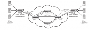
Figure 13: Components of a Frame Relay
The components of a frame relay as can be seen in the above figure are:
- Frame Relay Access Device or Frame Relay Assembler/Disassembler (FRAD): A device on the local area network, performing the task of modifying data packets. The header and the trailer information is also placed on the packets that are going out. The process of adding all this information to the data packets is known as encapsulation and stripping of the information at the receiving end is known as de-capsulation.
- Frame Relay Link: This component refers to the media that is used for connecting to the local network to the Frame Relay switch. This can be a T1/T3 link, ISDN or fiber.
- Frame Relay Switch: The frames are routed using the Frame Relay Switch. Before a frame gets to reach its destination, it may have to pass through many switches. It can be a part of a public or a private network.
- Backbone Media: The Frame Relay switches are connected using the backbone. T1/T3 links or even fiber is used for the backbone link. It follows a mesh topology. Mesh topology allows redundant links to interconnect to the Frame Relay Switches.
- Virtual Circuit: The starting point of a virtual circuit is the local network. It is connected to the FRAD on the receiving end. PVC is often a virtual link.
- Data Terminal Equipment (DTE): This is the terminating equipment located at the company’s network. It includes hardware as end user systems, servers, routers, bridges, and switches.
- Data Circuit-Terminating Equipment (DCE): The term DCE refers to the equipment that is owned by a carrier. It is responsible for the switching services for the network. This is actually responsible for transmitting the data.
- Data Link Connection Identifier (DLCI): This is the number that is used for identifying the logical circuit between the router and the Frame Relay switch.
Satellite
Internet facility is available through the satellite also. It is normally available where DSL, Internet through cable or broadband is not available. It is a connection, which is always available, and the claimed speed is 512Kbps for uploads and 2048Kbps for downloads. The drawback that is not allowing this technology to be popular is the cost factor. The advantage of the same is portability, which means that where ever one goes one can access the internet even if there is no phone line or cable.
The same is offered by many companies under different packages designed on the basis of price, speed and service. Internet Satellite Services can be:
- One Way: A satellite card and a satellite dish are required to form a one way connection. The satellite dish is installed at the user end. Outgoing requests are sent on one link using the phone line and inbound traffic returns on the satellite link.
- Two Way: A two way connection provides for incoming as well as outgoing traffic. This also requires a satellite card and a dish to form the connection.
Atmospheric conditions play a determining role in transmissions taking place using this technology
Broadband cable
Areas that have access to digital cable television can enjoy access to the Internet also using the cable connection. The advantages of using this technology are- it is reliable; it is pocket friendly. When this technology started the companies providing the service allowed unlimited data transfer but as the usage is increasing, ceilings are being put on the amount of data that can be transferred. Connectivity is established using a cable modem. The modem is turn uses a coaxial connection for connecting to the provider’s outlet and a UTP for attaching directly to the system. The modems are provided by the cable companies on a nominal fee. The modems are able to supply a 10Mbps Ethernet connection for the home LAN though actually it may be much less. The speed factor makes it less popular for use in businesses and offices. The biggest disadvantage of using this technology is that the bandwidth is shared with others in the area. As a result, the link may weaken during rush hours.
DSL/ADSL
Another Internet Access method is DSL. A standard phone line is used in this method to provide access at a high speed. It is not widely prevalent in today’s times and is expected to catch up as the use of broadband spreads. In this technology, data is transferred over a standard phone connection. It is preferred in homes and small to mid size business as at very reasonable costs it provides excellent services in terms of speed. It enables the use of a different frequency meaning that the phone line can be used while the internet is being used. It has many variations to it and the group taken cumulatively is known as xDSL. The reason behind having these variations is that the needs of the users differ and keeping these specific needs in mind, variations of the same technology have been designed. The variations are:
- Asymmetric DSL (ADSL): ADSL is the most popular the DSL varieties. The word asymmetric in the name represents the different bands on the line. One of the bands that is used for POTS deals with the analog traffic, a second band provides for upload access, while the third band takes care of downloads. With this form of technology, downloads take place much faster than uploads. The characteristics of ADSL are:
Upload Speed: 1Mbps
Download Speed: 8Mbps
Type: Asymmetric
- Symmetric DSL (SDSL): Using this variation the user can enjoy the same speed for uploads and as well as downloads. It is most suited for applications such as web hosting, intranets, and ecommerce. A phone line cannot be shared while using this technology. The characteristics of SDSL are:
Upload Speed: 1.5 Mbps
Download Speed: 1.5 Mbps
Type: Symmetric
- ISDN DSL (IDSL): This is a symmetric type of DSL. Environments where SDSL and ADSL are not available unavailable this variation is used. It does not support analog phones. The characteristics of IDSL are:
Upload Speed: 144 Kbps
Download Speed: 144 Kbps
Type: Symmetric
- Rate Adaptive DSL (RADSL): This is a variation on ADSL. The advantage of opting for this technology is that it can alter its transmission speeds based on the quality of the signal. It is asymmetric in nature and can support line sharing. The characteristics of RADSL are:
Upload Speed: 1Mbps
Download Speed: 7Mbps
Type: Asymmetric
- Very High Bit Rate DSL (VHDSL): This variation is an asymmetric version of DSL. A phone line can be shared using this technology. High bandwidth applications such as VoIP and HDTV are easily accommodated on this. Data rates up to 10Mbps and above are easily achieved and as a result, it is a fast form of DSL. The characteristics of VHDSL are:
Upload Speed: 1.6 Mbps
Download Speed: 10 Mbps+
Type: Asymmetric
- High Bit Rate DSL (HDSL): This is a symmetric version of DSL. It allows for identical transmission rates in both directions, that is, while receiving and sending data. Line sharing is not accommodated in this technology. The characteristics of HDSL are:
Upload Speed: 768 Kbps
Download Speed: 768Kbps
Type: Symmetric
DSL can be incorporated in two ways:
- A Shared Link: A shared link is one which supports both voice and internet services. This is made possible by the use of two frequencies: high (for voice) and low (for internet)
- A Dedicated Link: Though this technology has its advantages it is not a cost effective option. It is not used while making regular voice transmissions.
Adaptive Rate is a term, which is often used while discussing DSL technology. This connotes that the speed of the connection is fluctuating. Several factors like the distance existing between the provider of DSL and the Internet, physical condition of the line etc cause fluctuations.
ISDN
It is a dial up technology and can be used for transmitting voice and data at the same time and over the same physical connection. In this technology, access is available for users to digital communication. This communication is available via both packet switching and circuit switching connections.
It allows transmission of voice and data over telephone wires. The advantage of ISDN is that it much faster than a dial-up modems connection. Another advantage is that the connection is formed very quickly. The limitation is that a dedicated phone line is required even though it can be paid for through a monthly payment. These monthly payments exceed the costs involved in dial up connections.
For setting up an ISDN connection, the number is dialed just as in the case of a telephone call or a dial up modem connection. To bring the conversation to end, one end has to disconnect again just as in the case of a telephone connection.
In the case of ISDN, the same media is used as a PSTN or a regular wire. The method in which the media is used is much different. PSTN was designed for data transfer, a dial up modem is used for converting PSTN analog signals to digital signals. The problem that is faced is that no communication is converted to digital. The communication traveling from the telephone exchange to the modem is in an analog form and from the modem to the computer travels in a digital form. However, in the ISDN form, communication takes place in the digital form right from the ISDN exchange. Data is transferred at a much faster rate as the entire transfer is in the digital form. The figure illustrated below illustrates a comparison between PSTN Links and ISDN Links.
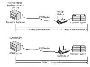
Figure 14: Comparison of PSTN and ISDN Communication
There are two defined interface standards- Basic Rate Interface (BRI) and Primary Rate Interface (PRI)
- Basic Rate Interface (BRI): A communication line that utilizes three separate channels is termed as BRI. The three channels are – 2 B channels of 64 Kbps, which carry digital information and 1 D channel of 16 Kbps for out of band signaling. To use this, the connection point must be within 5,486 meters of the providers BRI service center.
- Primary Rate Interface (PRI): This form of ISDN is carried over a T1 line. It consists of 23 B channels and is able to handle transmission rates of up to 1.536Mbps. Every channel provides 64Kbps for data/voice, and one 64Kbps D channel.
ATM
The ATM technology was introduced in the early 1990’s and was seen as a complete solution in itself for both LAN as well as WAN environments. Its use ranged from a desk top format to a remote system. The ATM technology did not deliver to the expected levels for the reasons of implementation costs as well as lack of standardization. The growth of ATM was further stunted by the popularity of Gigabit Ethernet.
It uses the packet switching technology and can make transmissions at a speed ranging from 1.544 Mbps at the lowest and 622 Mbps at the highest. It can perform its functions with both fixed length packets and variable length packets, but its performance is best derived by the use of fixed length. Fixed length packets also make into more flexible and adaptable to other technologies. Virtual connections are used by ATM networks for forming connections between end points. PVC’s or SVC’s can be used for setting up ATM’s.
PPP/Multilink PPP
It is a point-to-point Layer 2 protocol that is used on point-to-point links. PPP standards can be categorized into two main categories:
1) Features that do not relate to any Layer 3 protocol
2) Features specific to Layer 3 protocol
PPP’s Link Control Protocol (LCP) handles the feature related to specific Layer 3 protocol. When the PPP link comes up the LCP begins the parameter negotiation with the other end of link. LCP manages the control of which authentication protocol to use and in which order. After the successful completion of LCP negotiations LCP is considered up. LCP provides various tasks such as communication between the host and the client. LCP helps PPP to use authentication. PPP is now days replaced by SLIP because it provides error detection and data compression features. These features were not available in SLIP moreover PPP is very easy to configure.
There are various features that PPP provides are:
1) Error Detection
2) Error Recovery
3) Supports synchronous and asynchronous links
MPLS
Multiprotocol Label Switching (MPLS) is a technology designed to speed up network traffic flow by moving away from the use of traditional routing tables. Instead of routing tables, MPLS uses short labels to direct packets and forward them through the network. This is an important distinction. In a traditional packet-forwarding design, the packet travels from one router to the next, with a forwarding decision made at each hop along the way. The forwarding decision is based on the information in the IP packet header with the routing table. This packet has to be analyzed at each hop along the way. It was just a matter of time before a more efficient packet-forwarding method came into play.
GSM/CDMA
GSM and CDMA are competing wireless technologies with GSM enjoying about an 82% market share globally. In the U.S., however, CDMA is the more dominant standard. Technically GSM (Global System for Mobile communications, originally from Groupe Spécial Mobile) is a specification of an entire wireless network infrastructure, while CDMA relates only to the air interface — the radio portion of the technology.
Code division multiple access (CDMA) describes a communication channel access principle that employs spread-spectrum technology and a special coding scheme (where each transmitter is assigned a code). CDMA also refers to digital cellular telephony systems that use this multiple access scheme, as pioneered by QUALCOMM, and W-CDMA by the International Telecommunication Union (ITU), which is used in GSM’s UMTS.
Subscriber Identity Module (SIM Card)
SIM (subscriber identity module) card, the onboard memory device that identifies a user and stores all of his information on the handheld. You can swap GSM SIM cards between handsets when a new one is necessary, which enables you to carry all of your contact and calendar information over to a new handset with no hassle. CDMA operators answer this flexibility with their own service that stores user data, including phone book and scheduler information, on the operator’s database. This service makes it possible to not only swap over to a new handset with little trouble, but it also gives users the ability to recover contact date even if their phone is lost or stolen.
International Roaming with GSM and CDMA
Where international business travel is an issue, GSM leaps forward in the race for the title of “Most Accessible.” Because GSM is used in more than 74% of the markets across the globe, users of tri-band or quad-band handsets can travel to Europe, India, and most of Asia and still use their cell phones. CDMA offers no multiband capability, however, and therefore you can’t readily use it in multiple countries. However, certain phones like the iPhone 5 now have Quad-band GSM built in so they can be used overseas with special calling plans from carriers.
LTE/4G
LTE operates in some of the existing cellular bands as well as newer bands. Specific bands have been designated for LTE (see the table). Different carriers use different bands depending upon the country of operation and the nature of their spectrum holdings. Most LTE phones use two of these bands, and they aren’t the same from carrier to carrier. For instance, Verizon’s iPhone 5 uses different bands than AT&T’s iPhone 5.
Most of the bands are set up for frequency division duplexing (FDD), which uses two separate bands for uplink and downlink. The spacing between FDD channels in bands 1 through 28 varies considerably depending on carrier spectrum holdings. Bands 33 through 44 are used for time division duplexing (TDD), so the same frequencies are used for both uplink and downlink.
LTE is a broadband wireless technology that uses wide channels to achieve high data rates and accommodate lots of users. The standard is set up to permit bandwidths of 1.4, 3, 5, 10, 15, and 20 MHz. The carrier selects the bandwidth depending on spectrum holdings as well as the type of service to be offered. The 5- and 10-MHz widths are the most common. Some bandwidths cannot be used in different bands.
HSPA+
3G HSPA, High Speed packet Access is the combination of two technologies, one of the downlink and the other for the uplink that can be built onto the existing 3G UMTS or W-CDMA technology to provide increased data transfer speeds.
The original 3G UMTS / W-CDMA standard provided a maximum download speed of 384 kbps.
With many users requiring much high data transfer speeds to compete with fixed line broadband services and also to support services that require higher data rates, the need for an increase in the speeds obtainable became necessary.
This resulted in the development of the technologies for 3G HSPA.
HSPA features
The system provides an enhancement on the basic 3G WCDMA / UMTS cellular system, providing data transfer rates that are considerably in excess of those originally envisaged for 3G as well as much greater levels of spectral efficiency.
3G
3G is a generic term covering a range of future wireless network technologies, including WCDMA, CDMA2000, UMTS and EDGE.
3G combines high-speed mobile access with Internet Protocol (IP) based services. This doesn’t just mean fast mobile connection to the World Wide Web – by liberating us from slow connections, cumbersome equipment and immovable access points, 3G will enable new ways to communicate, access information, conduct business and learn. This is summarized in the diagram on below produced by Allied Business.
Dialup
A dial up modem is a device that lets your computer communicate with other computers by dialing a connection to the Internet over a telephone line.
A modem modulates outgoing digital signals from a computer to analog signals for transmitting over a conventional telephone line. It demodulates the incoming analog signals into a digital signal for the computer.
WiMAX
WiMAX is short for Worldwide Interoperability for Microwave Access, and it also goes by the IEEE name 802.16.
WiMAX has the potential to do to broadband Internet access what cell phones have done to phone access. In the same way that many people have given up their “land lines” in favor of cell phones, WiMAX could replace cable and DSL services, providing universal Internet access just about anywhere you go. WiMAX will also be as painless as Wi-Fi — turning your computer on will automatically connect you to the closest available WiMAX antenna.
A WiMAX system consists of two parts:
- A WiMAX tower, similar in concept to a cell-phone tower – A single WiMAX tower can provide coverage to a very large area — as big as 3,000 square miles (~8,000 square km).
- A WiMAX receiver – The receiver and antenna could be a small box or PCMCIA card, or they could be built into a laptop the way WiFi access is today.
A WiMAX tower station can connect directly to the Internet using a high-bandwidth, wired connection (for example, a T3 line). It can also connect to another WiMAX tower using a line-of-sight, microwave link. This connection to a second tower (often referred to as a backhaul), along with the ability of a single tower to cover up to 3,000 square miles, is what allows WiMAX to provide coverage to remote rural areas.
What this points out is that WiMAX actually can provide two forms of wireless service:
- There is the non-line-of-sight, WiFi sort of service, where a small antenna on your computer connects to the tower. In this mode, WiMAX uses a lower frequency range — 2 GHz to 11 GHz (similar to WiFi). Lower-wavelength transmissions are not as easily disrupted by physical obstructions — they are better able to diffract, or bend, around obstacles.
- There is line-of-sight service, where a fixed dish antenna points straight at the WiMAX tower from a rooftop or pole. The line-of-sight connection is stronger and more stable, so it’s able to send a lot of data with fewer errors. Line-of-sight transmissions use higher frequencies, with ranges reaching a possible 66 GHz. At higher frequencies, there is less interference and lots more bandwidth.
WiFi-style access will be limited to a 4-to-6 mile radius (perhaps 25 square miles or 65 square km of coverage, which is similar in range to a cell-phone zone). Through the stronger line-of-sight antennas, the WiMAX transmitting station would send data to WiMAX-enabled computers or routers set up within the transmitter’s 30-mile radius (2,800 square miles or 9,300 square km of coverage). This is what allows WiMAX to achieve its maximum range.
The final step in the area network scale is the global area network (GAN). The proposal for GAN is IEEE 802.20. A true GAN would work a lot like today’s cell phone networks, with users able to travel across the country and still have access to the network the whole time. This network would have enough bandwidth to offer Internet access comparable to cable modem service, but it would be accessible to mobile, always-connected devices like laptops or next-generation cell phones.
Metro-Ethernet
Metro Ethernet is the use of Carrier Ethernet technology in metropolitan area networks (MANs). Because it is typically a collective endeavor with numerous financial contributors, Metro Ethernet offers cost-effectiveness, reliability, scalability and bandwidth management superior to most proprietary networks.
Metro Ethernet can connect business local area networks (LANs) and individual end users to a wide area network (WAN) or to the Internet. Corporations, academic institutions and government agencies in large cities can use Metro Ethernet to connect branch campuses or offices to an intranet. A typical Metro Ethernet system has a star network or mesh network topology with individual routers or servers interconnected through cable or fiber optic media.
“Pure” Ethernet technology in the MAN environment is relatively inexpensive compared with Synchronous Digital Hierarchy (SDH) or Multiprotocol Label Switching (MPLS) systems of similar bandwidth. However, the latter technologies can be applied to Metro Ethernet in urban areas willing to devote the necessary financial resources to the task.
Leased lines
These are high speed lines that are available on lease from various telephone companies. These are used for transmitting both data as well as voice. The technology is referred to as T lines in the U.S.A, J lines in Japan and E lines in Europe. Mostly these are used for forming point to point networks. There are four types of carrier lines that are available:
- T-1: This line offers a transmission speed of 1.544Mbps and is mostly used for connecting LANs.
- T-2: This line offers a transmission speed of 6.312Mbps.
- T-3: This line offers a transmission speed of up to 44.73 6Mbps.
- T-4: This line offers a transmission speed of up to 274.176Mbps.
The most commonly used lines are the T-1 and T-3 lines.
- T-1 Line: The technology is referred to as T-1It is a dedicated digital circuit, which is leased by a telephone company. Its unique characteristic is that it is always available and open line between two points of contact. It is based on the technology known as multiplexing or muxing. This done by the use of a special device called the multiplexer. The limitation of one call per wire is not applicable due to multiplexing. The multiplexer divides the transmission into multiple transmissions, which are forwarded simultaneously. The signals are reassembled when they reach their destination. The advantages of this connection are- point-to-point communication; a constant connection; the data rates is up to 1.544 Mbps and the costs can be fixed. The disadvantage of this is that it is a costly affair to set up a point-to-point communication between two ends.
- T3 Line: Till a certain period of time the speed of 1.544 Mbps offered by the T-1 carrier line was sufficient, but as the needs of businesses started to increase so did the demand for speed. The answer to the demand for speed was T-3. It provided a speed of 44.736 Mbps. These provide very high and are preferred by large corporate houses and Internet service providers. The speed is the advantage and the cost is its limitation.
T-carrier is the designation for the technology used in the United States and Canada. In Europe, they are called E-carriers and in Japan, J-carriers. Table 1.1 describes the T/E/J carriers.
Name: Transmission Speed
T1: 1.544Mbps
T1C: 3.152Mbps
T2: 6.312Mbps
T3: 44.736Mbps
T4: 274.176Mbps
J0: 64Kbps
J1: 1.544Mbps
J1C: 3.152Mbps
J2: 6.312Mbps
J3: 32.064Mbps
J3C: 97.728Mbps
J4: 397.200Mbps
E0: 64Kbps
E1: 2.048Mbps
E2: 8.448Mbps
E3: 34.368Mbps
E4: 139.264Mbps
E5: 565.148mbps
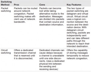
Circuit switch vs packet switch
The following table compares circuit switch and packet switch:
Recent Comments