N10-007 Given a scenario, implement and configure the appropriate addressing schema
IPv6
EUI-64
One of IPv6’s key benefits over IPv4 is its capability for automatic interface addressing. By implementing the IEEE’s 64-bit Extended Unique Identifier (EUI-64) format, a host can automatically assign itself a unique 64-bit IPv6 interface identifier without the need for manual configuration or DHCP. This is accomplished on Ethernet interfaces by referencing the already unique 48-bit MAC address, and reformatting that value to match the EUI-64 specification.
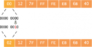
RFC 2373 dictates the conversion process, which can be described as having two steps. The first step is to convert the 48-bit MAC address to a 64-bit value. To do this, we break the MAC address into its two 24-bit halves: the Organizationally Unique Identifier (OUI) and the NIC specific part. The 16-bit hex value 0xFFFE is then inserted between these two halves to form a 64-bit address.
Why 0xFFFE? As explained in the IEEE’s Guidelines for EUI-64 Registration Authority, this is a reserved value which equipment manufacturers cannot include in “real” EUI-64 address assignments. In other words, any EUI-64 address having 0xFFFE immediately following its OUI portion can be recognized as having been generated from an EUI-48 (or MAC) address.
The second step is to invert the universal/local (U/L) flag (bit 7) in the OUI portion of the address. Globally unique addresses assigned by the IEEE originally have this bit set to zero, indicating global uniqueness. Likewise, locally created addresses, such as those used for virtual interfaces or a MAC address manually configured by an administrator, will have this bit set to one. The U/L bit is inverted when using an EUI-64 address as an IPv6 interface ID.
Again, you’re probably wondering why this is done. The answer lies buried in section 2.5.1 of RFC 2373:
The motivation for inverting the “u” bit when forming the interface identifier is to make it easy for system administrators to hand configure local scope identifiers when hardware tokens are not available. This is expected to be case for serial links, tunnel end-points, etc. The alternative would have been for these to be of the form 0200:0:0:1, 0200:0:0:2, etc., instead of the much simpler ::1, ::2, etc.
The important part to remember here is that the scope of the address never changes: global addresses are still global and local addresses are still local. Rather, the meaning of the bit is inverted for convenience, so the value of the bit must be inverted as well. We can see this conversion in action when we assign an IPv6 address to a router interface. First, take note of the interface’s MAC address (this is typically the same as its burned-in address, or BIA).
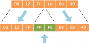
Router# show interface f0/0 FastEthernet0/0 is up, line protocol is down Hardware is Gt96k FE, address is 0012.7feb.6b40 (bia 0012.7feb.6b40) … After assigning an EUI-64-designated IPv6 address to the interface, we can verify that the interface ID has been drawn from the MAC address in the process described for both the assigned and the link local address:
Router(config)# interface f0/0 Router(config-if)# ipv6 address 2001:db8::/64 eui-64 Router(config-if)# do show ipv6 interface f0/0 FastEthernet0/0 is up, line protocol is down IPv6 is enabled, link-local address is FE80::212:7FFF:FEEB:6B40 [TEN] No Virtual link-local address(es): Global unicast address(es): 2001:DB8::212:7FFF:FEEB:6B40, subnet is 2001:DB8::/64 [EUI/TEN] …
Autoconfiguration
Since 1993 the Dynamic Host Configuration Protocol (DHCP) [1] has allowed systems to obtain an IPv4 address as well as other information such as the default router or Domain Name System (DNS) server. A similar protocol called DHCPv6 [2] has been published for IPv6, the next version of the IP protocol. However, IPv6 also has a stateless auto-configuration protocol [3], which has no equivalent in IPv4.
DHCP and DHCPv6 are known as stateful protocols because they maintain tables within dedicated servers. However, the stateless auto-configuration protocol does not need any server or relay because there is no state to maintain.
This article explains the IPv6 stateless auto-configuration mechanism and depicts its different phases.
Scope of IPv6 Addresses
Every IPv6 system (other than routers) is able to build its own unicast global address. A unicast address refers to a unique interface. A packet sent to such an address is treated by the corresponding interface—and only by this interface. This type of address is directly opposed to the multicast address type that designates a group of interfaces. Most of this article deals with unicast addresses. For simplicity, we will omit the unicast qualifier when there is no ambiguity.
Address types have well-defined destination scopes: global, site-local and link-local. Packets with a link-local destination must stay on the link where they have been generated. Routers that could forward them to other links are not allowed to do so because there has been no verification of uniqueness outside the context of the origin link.
Similarly, border-site routers cannot forward packets containing site-local addresses to other sites or other organizations. The IETF is currently working on a way to remove or replace site-local addresses. Hence, this article will refrain from any other reference to this address type. Finally, a global address has an unlimited scope on the worldwide Internet. In other words, packets with global source and destination addresses are routed to their target destination by the routers on the Internet. A fundamental feature of IPv6 is that allNetwork Interface Cards (NICs) can be associated with several addresses.
At minimum, a NIC is associated with a single link-local address. But in the most common case a NIC is assigned a link-local and at least one global address. The following command displays the configuration of network interface eth1 on a Red Hat system. This interface is associated with two IPv6 addresses. One of them starts with fe80:: and the other with 3ffe:. The scope of the first one is the link and the second has a global scope.
root# ip address list eth1
3: eth0: <broadcast,multicast,up mtu 1500 qdisc pfifo_fast qlen 100
link/ether 00:0c:29:c2:52:ff brd ff:ff:ff:ff:ff:ff
inet6 fe80::20c:29ff:fec2:52ff/10 scope link
inet6 3ffe:1200:4260:f:20c:29ff:fec2:52ff/64 scope global
Creation of the Link-Local Address
An IPv6 address is 128 bits long. It has two parts: a subnet prefix representing the network to which the interface is connected and alocal identifier, sometimes called token. The subnet prefix is a fixed 64-bit length for all current definitions. Because IPv4 manual configuration is a well-known pain, one could hardly imagine manipulating IPv6 addresses that are four times longer. Moreover, a DHCP server is not always necessary or desired; in the case of a remote control finding the DVD player, a DHCP environment is not always suitable.
Because the prefix length is fixed and well-known, during the initialization phase of IPv6 NICs, the system builds automatically a link-local address. After a uniqueness verification, this system can communicate with other IPv6 hosts on that link without any other manual operation.
IPv4
For a network using the TCP/IP protocol, each system needs to have a unique address. The address not only defines the network to which the device is connected, but also the address of the node on the network. It is mandatory for each device to share the same network address but different node address. The job of differentiating between the network address and the node address comes under the purview of a subnet mask. Without the differentiation done by the subnet mask, the IP address is nothing more but a number.
An IPv4 address comprises of four sets of 8 bits, or octets. It comes out to be a 32 bit address in length. A decimal value is assigned to every bit in each octet. The values are assigned from left to right, with the leftmost having the highest value of 128, which is followed by 64, 3 2, 1 6, 8, 4, 2, and 1, as one goes right.
Values are attached to every bit in the octet following the binary system, that is, the value of a bit can be a 1 or a 0. The decimal value of every 1 is counted, whereas the 0 are ignored. This numbering system is called binary. If the value is 1, it is counted as its equivalent decimal value, and if it is 0, it is ignored. This means that if all the bits are 0, the value of the octet is 0. If all the bits in the octet are 1, the value of the octet will be 255. The value 255 is derived by adding up 128+64+32+16+8+4+2+1. The binary to decimal conversions are depicted in the table given below.
| Decimal Value | 128 | 64 | 32 | 16 | 8 | 4 | 2 | 1 |
| Binary Value | 1 | 1 | 1 | 1 | 1 | 1 | 1 | 1 |
Figure 43: Binary to Decimal Conversion
By using the set of 8 bits and manipulating the 1s and 0s, any value between 0 and 255 can be obtained for each octet. Table 5.2 shows a few examples of this.
The address is arranged in four sets of bits, with each set separated from the other by using period. IP addresses are grouped in classes. Classes are based on logical divisions. There are five classes: A, B, C, D, and E available in IPv4 address. For assigning addresses to clients only the first three classes are used. A fixed length subnet mask is used each for differentiating between the network address and the node address. The first octet is used by a Class A addresses, two octets are used by a Class B addresses, and three octets are used by a Class C addresses. This results in Class A having a small number of network addresses but a large number of host addresses. Class B has larger number of networks but smaller number of hosts. Class C has even a larger number of networks and a smaller number of hosts. Whereas Class E is reserved for future development, Class D is reserved for multicast addressing. The numbers are represented in the table given below:
| Address Class | Range | Number of Networks | Number of Hosts/Network | Binary Value of First Octet |
| A | 1-126 | 126 | 16,777,214 | 00000001-01111110 |
| B | 128-191 | 16384 | 65,534 | 10xxxxxx |
| C | 192-223 | 2,097,152 | 254 | 110xxxxx |
| D | 224-239 | N.A | N.A. | 1110xxxx |
| E | 240-255 | N.A | N.A. | 1111xxxx |
Table 5: IPv4 Address Classes and the Number of Available Network/Host Addresses
The network number 127 is kept as reserved for a local loopback. The local loopback is a function built in to the TCP/IP protocol. It is an inbuilt function in the TCP/IP protocol suite and can be used for troubleshooting.
Private vs public
A network to which anyone can connect is known as a public network. The best example of this is the internet. A private network is network to which access is restricted. The best example of this type would be a corporate network or a school network. The addressing of a device on a public network has to done very carefully. It is mandatory for hosts communicating using TCP/IP to have unique addresses. The address is the logical network each host belongs to along with the host’s address on the network. An internetwork private in nature with three logical networks and 100 nodes on each is not much to handle when it comes to addressing, but the considerations cannot be the same for a network of the scale of internet.
A unique address, known as a registered address for every device, has to be assigned, as it is assigned to a specific party. In case a duplication of the address occurs for devices, it is almost certain that none would be able to communicate. Hence it is to be done very carefully and is a controlled matter. Initially, it was the responsibility of IANA to assign these addresses, but it has gone ahead and delegated some of its responsibilities to other organizations. Primarily, the responsibility rests with three organizations:
- The American Registry for Internet Numbers (ARIN);
- The Asia Pacific Network Information Centre (APNIC); and
- Réseaux IP Européens Network Coordination Centre (RIPE NCC).
A valid registered IP address has to be obtained from any of these organizations for connecting a system directly to the internet. Addresses are also obtainable from the Internet Service Provider.
Private Address Ranges: For private use address ranges have been set aside.. These are called private ranges as these been specifically allocated fro private networks. The internet routers are configured in a manner that they ignore, when they come across packets with these addresses. It would actually be stopped right at the first router.
In RFC 1918, three private ranges are defined one each from each class, that is, Class A, B and C. Classes A and B offer more options for addressing than Class C.
| Class | Address Range | Default Subnet Mask |
| A | 10.0.0.0 – 10.255.255.255 | 255.0.0.0 |
| B | 172.16.0.0 – 172.31.255.255 | 255.255.0.0 |
| C | 192.168.0.0 – 192.168.255.55 | 255.255.255.0 |
Table 3: Private Address Range
Practical Uses of Public and Private IP Addressing: Generally, companies have a few registered IP addresses for Internet use and a large number of private IP addresses for private use. The figure given below illustrates with the help of a simple example:
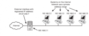
Figure 45: Example illustrating Public and Private Network Address Assignments.
The network shown in the above example provides Internet access to the clients through a proxy server system. The registered IP addresses of the external interface of the proxy server will be available. The systems on the internal network will use one from the private range.
NAT/PAT
The principle governing NAT is that many computer systems can take the shelter of a single IP address. This is done for the reason that there is a shortage of IP addresses. Using NAT, it becomes possible that one registered IP address is used on the external interface of the system. Between the internal and the external system, this system acts as a gateway. NAT allows the flexibility of exercising choice of addressing scheme on the internal networks.
When a NAT service is being performed, it funnels the requests that are made to it to the internet. A remote host takes the request to be from a single address. NAT keeps a record of the source of particular requests and returns the data received to the correct system. Servers providing NAT functionality keep a track of the source of request by statically mapping a particular internal address in relation to a specific external one. This ensures that the outgoing requests carry the same IP address. The figure given below illustrates the working of NAT.
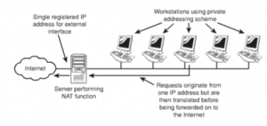
Figure 46: Working of NAT
There are few variations of NAT that are available, the variations are:
- PAT: PAT is a variation of NAT that ensures that all systems on the LAN are translated to an identical IP address but different port number. Incase of usage of the internet by multiple clients PAT can be used. There being a dearth of public IP addresses, it is required that the clients on the internal system be mapped to a single public IP address. Packets when received back into the private network are routed to their destinations after referring to a table within PAT. The table keeps a record of the public and private port numbers.
- SNAT and DNAT: SNAT and DNAT are variations of NAT. SNAT works by mapping a private IP address. It maps the address directly to a static unchanging public IP address. With this the internal system is able to have an unregistered private IP address. In spite of this it is still accessible over the Internet.
In DNAT a private IP address is mapped to a public IP address. This is done using a cache of public IP addresses.
MAC addressing
It is important to understand the basic concepts of MAC addressing for a network administrator.
It is a 6 byte or in other words a 48 bit hexadecimal address. It allows NIC to be identified with a unique address. Irrespective of the protocol, it forms the basis of communication in a network. It has to ensure that no duplication of a MAC address takes place. To deal with this the assignment of MAB addresses is done by the Institute of Electrical and Electronics Engineers (IEEE).The IEEE followed a mechanism in which every manufacturer was assigned an ID and then allowing the manufacturer to allocate the ID’s. As a result the first three bytes denote the manufacturer and the rest of the three are allocated by the manufacturer. The last three are known as Organizational Unique Identifier or OUI in short. Looking at an example; in the address 00:D0: 59:09:07:51; 00:D0:59 are the first three bytes and stand for the manufacturer and 09:07:51 are the OUI.
There are different ways of finding out the MAC address of the NIC. The method undertaken to find out depends on the system or the platform on which work is being done.
Multicast: It is based on the technique, which allows sending and receiving of data between the members of a group at a given point of time. The messages are sent to the entire group at one time than being sent individually.
Unicast: Specification of a single address is done in these types of addresses. It is a point to point to link and the data is sent to a specific node identified by the address.
Broadcast: Broadcast is an absolute opposite of unicast addressing. It allows for targeting a number of networks at the same time. It is transmitted to everyone present on the network.
Broadcast domains vs collision domains
A broadcast address is at the opposite end of the spectrum from a unicast address. A broadcast address is an IP address that you can use to target all systems on a subnet or network instead of single hosts. In other words, a broadcast message goes to everyone on the network. A broadcast address is at the opposite end of the spectrum from a unicast address. A broadcast address is an IP address that you can use to target all systems on a subnet or network instead of single hosts. In other words, a broadcast message goes to everyone on the network.
Collision domain A segment of an Ethernet network between managing nodes, where only one packet can be transmitted at a time. Switches, bridges, and routers can be used to segment a network into separate collision domains.
Recent Comments