N10-007 Given a scenario, configure a switch using proper features
VLAN
This is a group of connected computers that act work in the same manner as they would in their own network segments. This model creates logical segments of a network as a result the administrator enjoys greater amount of flexibility beyond the physical design and infrastructure. It allows better management as the network is classified in sections. This model allows isolation of segments and hence is a more secure model. The advantages of this model are: It ensures an enhanced level of security. It reduces traffic that passes through the network. The job of the administrator becomes easy as the system is better organized.
Default VLAN
At the initial boot up of the switch, All switch ports become a member of the default VLAN, which makes them all part of the same broadcast domain. This allows any network device connected to any of the switch port to communicate with other devices on other switch ports.
On Cisco switches the default VLAN is VLAN 1. VLAN 1 has all the features of any VLAN, except that you cannot rename or delete it.
Data VLAN
A data VLAN that can also be referred to as user VLAN. This is configured to carry only user-generated traffic. The importance of separating user data from other type of VLAN is proper switch management and control.
Native VLAN
A native VLAN is assigned to an 802.1Q trunk port. An 802.1Q trunk port supports traffic coming from many VLANs as well as traffic that do not come from a VLAN. The 802.1Q trunk port places untagged traffic (traffic that does not come from a VLAN) on the native VLAN. In summary, the native VLAN observes and identifies traffic coming from each end of a trunk link.
Spanning tree (802.1d)/rapid spanning tree (802.1w)
An Ethernet network can have only a single active path between devices on a network. When multiple active paths are available, switching loops can occur. Switching loops are simply the result of having more than one path between two switches in a network. Spanning Tree Protocol (STP) is designed to prevent these loops from occurring.
STP is used with network bridges and switches. With the help of Spanning Tree Algorithm (STA), STP avoids or eliminates loops on a Layer 2 bridge.
STA enables a bridge or switch to dynamically work around loops in a network’s topology. Both STA and STP were developed to prevent loops in the network and provide a way to route around any failed network bridge or ports. If the network topology changes, or if a switch port or bridge fails, STA creates a new spanning tree, notifies the other bridges of the problem, and routes around it. STP is the protocol, and STA is the algorithm STP uses to correct loops.
If a particular port has a problem, STP can perform a number of actions, including blocking the port, disabling the port, or forwarding data destined for that port to another port. It does this to ensure that no redundant links or paths are found in the spanning tree and that only a single active path exists between any two network nodes.
STP uses bridge protocol data units (BPDUs) to identify the status of ports and bridges across the network. BPDUs are simple data messages exchanged between switches. BPDUs contain information on ports and provide the status of those ports to other switches. If a BPDU message finds a loop in the network, it is managed by shutting down a particular port or bridge interface.
Redundant paths and potential loops can be avoided within ports in several ways:
- Blocking: A blocked port accepts BPDU messages but does not forward them.
- Disabled: The port is offline and does not accept BPDU messages.
- Forwarding: The port is part of the active spanning tree topology and forwards BPDU messages to other switches.
- Learning: In a learning state, the port is not part of the active spanning tree topology but can take over if another port fails. Learning ports receive BPDUs and identify changes to the topology when made.
- Listening: A listening port receives BPDU messages and monitors for changes to the network topology.
Most of the time, ports are in either a forwarding or blocked state. When a disruption to the topology occurs or a bridge or switch fails for some reason, listening and learning states are used.
Interface configuration
Trunking/802.1q
In computer networking, the term trunking refers to the use of multiple network cables or ports in parallel to increase the link speed beyond the limits of any one cable or port. Sound confusing? If you have network experience, you might have heard the term link aggregation, which is essentially the same thing. It is just using multiple cables to increase the throughput. The higher capacity trunking link is used to connect switches to form larger networks.
VLAN trunking—or VLAN (trunking), as CompTIA lists it—is the application of trunking to the virtual LAN—now common with routers, firewalls, VMWare hosts, and wireless access points. VLAN trunking provides a simple and cheap way to offer a nearly unlimited number of virtual network connections. The requirements are only that the switch, the network adapter, and the OS drivers all support VLANs. The VLAN Trunking Protocol (VTP) is a proprietary protocol from Cisco for just such a purpose.
Port Mirroring
You need some way to monitor network traffic and monitor how well a switch works. This is the function of port mirroring. To use port mirroring, administrators configure a copy of all inbound and outbound traffic to go to a certain port. A protocol analyzer examines the data sent to the port and therefore does not interrupt the flow of regular traffic.
VLAN assignment
Another consideration to keep in mind is that membership to a VLAN can be assigned both statically and dynamically. In static VLAN assignment, the switch ports are assigned to a specific VLAN. New systems added are assigned to the VLAN associated with that particular port. For example, if you plug a new system into port 8, the user becomes part of the administrator’s network. So you must ensure that you have the right port assigned to users.
Dynamic VLAN assignment requires specific software to control VLAN distribution. Using a VLAN server, administrators can dynamically assign VLAN membership based on criteria such as a MAC address or a username/password combination. As a system tries to access the network, it queries the VLAN server database to ask for VLAN membership information. The server responds and logs the system onto the appropriate VLAN network. When correctly configured, dynamic assignment reduces the human error associated with static VLAN assignment.
Default gateway
Default gateways are the means by which a device can access hosts on other networks for which it does not have a specifically configured route. Most workstation configurations actually default to just using default gateways rather than having any static routes configured. This enables workstations to communicate with other network segments, or with other networks, such as the Internet.
When a system wants to communicate with another device, it first determines whether the host is on the local network or a remote network. If the host is on a remote network, the system looks in the routing table to determine whether it has an entry for the network on which the remote host resides. If it does, it uses that route. If it does not, the data is sent to the default gateway.
PoE and PoE+ (802.3af, 802.3at)
The purpose of Power over Ethernet (PoE) is pretty much described in its name. Essentially, PoE is a technology that enables electrical power to transmit over twisted-pair Ethernet cable. The power transfers, along with data, to provide power to remote devices. These devices may include remote switches, wireless access points, voice over IP (VoIP) equipment, and more.
One of the key advantages of PoE is the centralized management of power. For instance, without PoE, all remote devices need to be independently powered. In the case of a power outage, each of these devices requires an uninterruptible power supply (UPS) to continue operating. A UPS is a battery pack that enables devices to operate for a period of time. With PoE supplying power, a UPS is required only in the main facility. In addition, centralized power management enables administrators to power up or down remote equipment.
Managed vs. unmanaged
Wireless networks typically are implemented using one of two wireless topologies:
- Infrastructure, or managed, wireless topology
- Ad hoc, or unmanaged, wireless topology
Infrastructure Wireless Topology
The infrastructure wireless topology is commonly used to extend a wired LAN to include wireless devices. Wireless devices communicate with the wired LAN through a base station known as an access point (AP) or wireless access point. The AP forms a bridge between a wireless and wired LAN, and all transmissions between wireless stations, or between a system and a wired network client, go through the AP. APs are not mobile and must stay connected to the wired network; therefore, they become part of the wired network infrastructure (thus the name). In infrastructure wireless networks, there might be several access points providing wireless coverage for a large area or only a single access point for a small area, such as a single home or small building.
Ad Hoc Wireless Topology
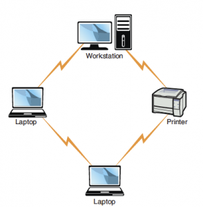
In a wireless ad hoc topology, devices communicate directly between themselves without using an access point. This peer-to-peer network design is commonly used to connect a small number of computers or wireless devices. For example, an ad hoc wireless network may be set up temporarily between laptops in a boardroom or to connect systems in a home instead of using a wired solution.
The ad hoc wireless design provides a quick method to share files and resources between a small number of systems. Figure 1.7 shows an ad hoc wireless network, and Figure 56 shows the infrastructure network using the AP
Figure 56: Ad Hoc wireless technology
Recent Comments