N10-007 Given a scenario, troubleshoot and resolve common fiber cable issues
Attenuation/Db loss
The loss of signal strength was introduced. This loss is measured in terms of decibels (dB). There will always be a difference in strength between what leaves the transmitter and what arrives at the receiver with every element (connectors, splitters/splices, and so on) causing a portion of that loss.
You can test dB loss using a power meter, or even a loopback test. If the loss is too high, look at replacing the components contributing to the problem (replace connectors with those having less loss, reduce the number of splices, and so on).
SFP/GBIC – cable mismatch
A bad route is any that you cannot rely upon to deliver packets. This can be related to lost data, timeouts, or simply unreliable connections. When bad or missing routes are discovered, route poisoning can be used to prevent them from being used. Route poisoning sets the hop count on that route to a high number (16 or infinite are common values) and prevents it from being used.
Bad SFP/GBIC – cable or transceiver
On routers, Small Form-Factor Pluggable modules (SFPs) and Gigabit Interface Converter modules (GBICs) are often used to link a gigabit Ethernet port with a fiber network (often 1000BASE-X). Both SFPs and GBICs exist for technologies other than fiber (Ethernet and Sonet/SDH are usual), but connecting to fiber has become the most common use. With either an SFP or GBIC, there is a receiver port (RX) and transmitter port (TX). These devices are static-sensitive as well as dust-sensitive. Care should be taken to not remove them more often than absolutely necessary to keep from shortening their life. After a module goes bad, they can be swapped for a new one to resolve the problem.
Wavelength mismatch
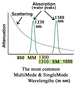
Wavelengths typically range from 800 to 1600 nm (nano-meters, where 1 nm = 1 billionth of a meter = 10-9 meters. You may see 633 and 780 nm from time to time, but by far the most common wavelengths actually used are 850 & 1300 for MultiMode fiber, and 1310 and 1550 nm for SingleMode fiber
There are many complex reasons for the selection of those particular wavelengths. But the main reason is that the Scattering/Absorption is low at those frequencies/wavelengths. In the chart below, it becomes evident that there are three low-lying areas of absorption, and an ever-decreasing amount of scattering as wavelengths increase. As you can see, all three popular wavelengths have almost zero absorption. However, 1550 nm waves suffer from much less scattering than 850 nm.
One Wavelength Defined – a wavelength is the distance between the peaks of two consecutive cycles of a sine wave, or between any two identical positions of the recurring pattern, as shown below:
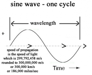
Frequency and Wavelength are inversely proportional, and are a function of the speed of propagation..
For example, light and radio waves are waves of electric and magnetic energy that travel through space at the speed of light, which is approximately 300 million meters per second. The distance a signal travels during one complete cycle is a wavelength. The speed or velocity of a wave (meters/sec) is equal to its wavelength (meters) times its frequency (Hz):
v = wf
w = v/f = 300,000,000/f
f = v/w = 300,000,000/w
Now, to make this simpler, since light wavelengths are normally given in nm (nano-meters), which is .000000001 meter, we can rewrite the equations in terms of w in nm :
w (nm) =
If we measure a radio wave’s frequency in megahertz (MHz), and its wavelength in meters,
wavelength X frequency = 300
Using this formula, we can determine the wavelength if we know the frequency, or the frequency if we know the wavelength.To find the frequency, divide the wavelength into 300. The frequency of a 6 meter wave is 300 / 6 = 50 MHz
The most common wavelengths for fiber-optic light is 1310 and 1550 nm (nm = nano-meter, which is 1 billionth of a meter). 1 nm = 10-9 meters.
Fiber type mismatch
OTDR (Optical time-domain reflectometer) is classic fiber optic test equipment used to characterize an optical fiber. It is most easy to use but it is also one of the most expensive, OTDR could give you an overview of the whole system you test. OTDR may be used for estimating the fiber optic cable length and fiber optic cable overall attenuation. It may also be used to locate faults, such as breaks, bend and so on by measuring the return loss. The common types of OTDR-like test equipment are: Full-feature OTDR, Hand-held OTDR, Fiber Break Locator, RTU in RFTSs.
Fiber Type mismatching is mean OTDR’s guide optical fiber is different with the under test Optical fiber core. In the while, measurement results of optical fiber vertical axis will be inaccurate. Transverse measurement accuracy.
The reason of Fiber Type mismatching, when the light incident from the Core diameter small optical fiber to the fiber core diameter larger core diameter optical fiber, the large core diameter fiber can not be incident light is completely full, so measurement error caused loss parameter.
The method of eliminate fiber Type mismatching is choosing right instrument guidance optical fiber, so that measured optical fiber and guide optical fiber phase matching. Such as, use single mode guiding fiber optic measuring single mode fiber, use multimode guide optical fiber measurement multimode fiber. Perhaps, select the corresponding guiding fiber according to the measured Optical fiber type and size. Ingellen is a leading manufacturer and supplier of OTDR. All of the OTDR are tested in-house prior to shipping to insure that they will arrive in perfect physical and working condition. And they guarantee the OTDR to work in your system and all of fiber optic products coming with a lifetime advance replacement warranty.
Dirty connectors
Cleaning. Not exactly a hot, cutting edge topic – right? But, dirty connector end faces may very well be the biggest cause of failures in the field for fiber optic links today. This is a topic that many people in the industry spend a lot of time on – much of it behind the scenes. Companies continue to produce new cleaning products, update their cleaning procedures and invest in equipment to inspect connectors before installation.
Face it, in the case of a fiber optic link, cleanliness may indeed be next to Godliness! There was a webinar last month where USConec presented some interesting information about end face dirt and cleaning tools for connectors. We have heard of users rejecting product before doing loss testing because their initial test is a pass/fail visual inspection – probably more often failing from dirt than real scratches and marks. The FOA has a “Tech Topic” page devoted to this, along with links to more information. Corning posted a youtube video all about cleaning the end of a ferrule – and it is over 5 minutes long. Cisco has a document on their website entitled “Inspection and Cleaning Procedures for Fiber-Optic Connections” and it takes hitting my ‘page down’ button 33 times to get to the end. Now that is a lot of cleaning information!
USConec has recently introduced new connector cleaners – adding to their popular IBC Cleaners line. New units for cleaning duplex LCs, MTRJ, all single fiber connectors as well as TFOCA connectors. These can be used to clean connectors before mating and when already loaded into adapters.
In the end, this is an important topic and not something that should be an after-thought for anyone dealing with fiber connectors. Whether you terminate connectors, write specs for them, install them or use them in any way – make sure you have planned a way to clean them and everyone who handles them understands the importance of doing so. This means doing something every time you have to mate a connector pair. It’s important.
Connector mismatch
To explore the results of fiber mismatch, let’s examine a scenario in which you connect the wrong-sized test cord to the cabling, and you are testing with an LED source. Let’s assume you are testing a 50-micron optical-fiber cabling plant for 100Base-FX and you have mistakenly picked up 62.5-micron test cords. Unknowingly, you have a mismatch of the fiber cores at the connection of the source test cord and the cabling. When launching light into the cabling, a significant amount of that light is lost as it hits the fiber cladding, resulting in loss.
This situation is analogous to a copper-cabling situation in which you connect a Category 3 patch cord to Category 5 cabling. The result for this copper channel is that it will not perform to Category 5 specifications. In the mismatched fiber scenario, the increased loss resulting from the use of inappropriate test cords is 4.7 dB.
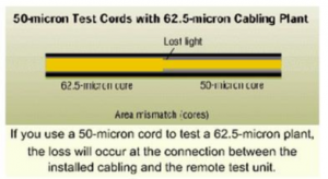
Now let’s examine a scenario in which you are testing a 62.5-micron cabling plant with an LED source, and you mistakenly use 50-micron test cords. In this situation, you will not have the loss impact at the connection between the source test cord and the cabling that you had in the first scenario. Loss, however, will show up at the far end, where the tester’s cord is connected to the cabling. Once again, as a result of mismatched fiber cores, you will find the loss values increased about 4.7 dB.
Bend radius limitations
Probably the most common mistake of inexperienced fiber installers is to violate minimum bending radius by making tight bends in the cable. Fiber cable is often so flexible that you can wrap it around your hand to pull or yank on it. Don’t! Tight bends, kinks, knots, etc., in fiber cable can cause microcrazing or growth of flaws in the fiber, with resulting loss of performance.
Minimum bending radius in traditional fiber cable is usually in the range of 20 times cable OD, considerably higher than electrical cable. However, new fiber technologies are lowering this minimum bend radius. Again, the specific minimum bending radius for a particular cable should be researched in the cable manufacturer’s specifications. This bending radius must be considered by the engineer when specifying conduit bends and pull box openings or sizing guide pulleys, sheaves, mid-assist capstans, etc.
Distance limitations
Very high data rates cannot travel far without regeneration. For example, the new 10 Gigabit Ethernet (10 Gbps is approx OC-192, and 1 Gbps is approx OC-24) can only travel a few hundred meters max. The newest fiber is called “laser-optimized fiber”, and it can support 550 meters for 10Gbps, or 1100 meters for 1Gbps. Of course, it requires excellent transmitter/receiver equipment as well to achieve those distances. Think about that – only 550 meters!! That means if a provider wants to build a nationwide, 10 Gbps backbone, they need to install thousands of expensive repeaters and regens !! This gives you an idea, why fiber networks are so expensive.
Well, actually there is a way to reduce the cost dramatically. Instead of installing pure OC-48 (2.5 Gbps) or OC-192 (10 Gbps) systems, the provider can install OC-48c or OC-192c systems. The “c” stands for “concatenation”, and this means that several fibers or several wavelengths on one fiber are used at lower speeds, and then concatenated at the endpoints. For example
Metro fiber systems (within a city) typically use CWDM (Course Wave-Division Multiplexing), and can only travel 5 km or so before requiring amplification and/or regeneration of the signal. Long-haul, intercity fiber uses DWDM (Dense Wave Division Multiplexing), which is much more expensive because it is tightly controlled and high-quality and carries more channels (more colors of light) – and it can carry a signal quite a distance — perhaps 42 to 60 miles (70 to 100 km). Undersea fiber systems use very expensive transmitters and cabling, and can travel up to 400 miles before requiring amplification/regeneration. On a long distance line, there is an equipment hut every 40 to 60 miles. The hut contains equipment that picks up and retransmits the signal down the next segment at full strength.
Recent Comments