N10-007 Given a scenario, troubleshoot and resolve common network issues
Incorrect IP configuration/default gateway
The default gateway configured on the router is where the data goes after it leaves the local network. Although many routes can be built dynamically, it is often necessary to add the first routes when installing/replacing a router. The ip route command can be used on most Cisco routers to do this from the command line, or most routers include a graphical interface for simplifying the process.
When you have the gateway(s) configured, use the ping and tracert/traceroute utilities to verify connectivity and proper configuration.
Broadcast storms/switching loop
“Addressing and Routing,” that a broadcast addresses is an IP address that you can use to target all systems on a subnet or network instead of single hosts. In other words, a broadcast message goes to everyone on the network. A broadcast storm occurs when a network is overwhelmed with constant broadcast or multicast traffic. Broadcast storms can eventually lead to a complete loss of network connectivity as the network is bogged down with the broadcast storm. As with other network problems, you may suspect a broadcast storm when network response times are poor and people are complaining about the slow network. These broadcast storms can be caused by faulty hardware such as a NIC that continually sends data, switching loops, or even faulty applications running on the network. Baselines work well for identifying broadcast storms.
Switching Loop
An Ethernet network can have only a single active path between devices on a network. When multiple active paths are available, switching loops can occur. Switching loops are simply the result of having more than one path between two switches in a network. Spanning Tree Protocol (STP) is designed to prevent these loops from occurring. If the packet in the loop is a broadcast message, the loop can create a full broadcast storm. Switching loops occur at the data link layer (Layer 2) of the OSI model.
Duplicate IP
Every IP address on a network must be unique. This is true not only for every host, but for the router as well, and every network card in general. The scope of the network depends on the size of the network that the card is connected to; if it is connected to the LAN, the IP address must be unique on that LAN, whereas if it is connected to the Internet, it must be unique on it.
Speed and duplex mismatch
When configuring a client for the network, you need to be aware of two more settings: port speed and duplex settings. These are adjusted in Windows in the Network Properties area. Figure 11.3 shows the port speed and duplex settings of a Windows system.
You have several choices for port speed and duplex settings (refer to Figure 70). You can choose Auto Negotiation to detect the setting that the network uses. You also can choose one of the other settings to match the network configuration, such as 100Mbps Half Duplex. If you work with a client system that is unable to log on to a network, you might need to ensure that the duplex setting and port speeds are correctly set for the network.
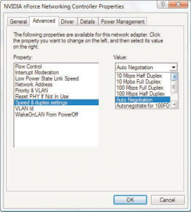
FIGURE 70: The port speed and duplex settings on a Windows system.
Incorrect VLAN assignment
Computer systems can be located anywhere on the network but communicate as if they are on the same segment. For example, networks with VLANs can be segmented according to an organization’s departments, such as sales, finance, and secretaries, or can be segmented according to usage, security permissions, and more.
Segmenting the network offers some clear advantages. It provides increased security because devices can communicate only with other systems in the VLAN. Users can see only the systems in their VLAN segment. This can help control broadcast traffic and makes it easier to move end systems around the network.
Problems can arise when users are moved or otherwise connected to the wrong VLAN. Administrators have to ensure that the user system is plugged into the correct VLAN port. For example, suppose a network is using port based VLANs to assign ports 1 through 8 to marketing, ports 9 through 18 to sales, and so on. Plugging a sales client into port 6 would make that sales client part of the marketing network. This sounds simple, but if the documentation is not up to date and you work with a new network, this can be tricky to identify.
One of the keys to preventing VLAN assignment errors is to clearly document the VLAN arrangement. If systems are moved, you need to know how to reconnect them and forward them to the correct VLAN port.
Another consideration to keep in mind is that membership to a VLAN can be assigned both statically and dynamically. In static VLAN assignment, the switch ports are assigned to a specific VLAN. New systems added are assigned to the VLAN associated with that particular port. For example, if you plug a new system into port 8, the user becomes part of the administrator’s network.
So you must ensure that you have the right port assigned to users.
Dynamic VLAN assignment requires specific software to control VLAN distribution. Using a VLAN server, administrators can dynamically assign VLAN membership based on criteria such as a MAC address or a username/password combination. As a system tries to access the network, it queries the VLAN server database to ask for VLAN membership information. The server responds and logs the system onto the appropriate VLAN network. When correctly configured, dynamic assignment reduces the human error associated with static VLAN assignment.
Hardware failure
Network hardware failure accounted for 36 percent of mobile Internet outages last year. This is a problem people need not have. Further, 35 percent of fixed Internet connections were affected as well. According to the European Network and Information Security Agency, malicious attacks, human errors, natural disaster, system and third party failures account for the damage caused to networks. It takes into account 79 incidents over the span of 18 countries.
While cyber attacks typically result in only a three-hour power outage, storms produced an average downtime of 84 hours last year. And in relation to network overload, last year an average of nine million users were affected during each outage.
For a company, a network outage can be devastating due to the overall number of employees that are affected during downtime. A Fortune 500 company typically loses about 1.6 hours every week due to downtime, and a total of $46 million every year in associated labor costs. When additional factors such as natural disasters take place, this number can jump even higher.
The easiest way to prepare for a disaster, therefore, is to have a backup plan so that your sensitive fiber channel over Ethernet is not compromised during downtime.
Power failure/power anomalies
Because the router serves as the gateway from your network to the rest of the world, it is imperative that it stays up and running. Just as an uninterruptible power supply (UPS) and backup power supplies should be used with miss-ioncritical servers, the same should be used with routers.
MTU/MTU black hole
A condition known as a black hole can occur when a router does not send back an expected message that the data has been received. It is known as a black hole from the view that data is being sent, but is essentially being lost.
This condition occurs when the packet the router receives is larger than the configured size of the Maximum Transmission Unit (MTU) and the Do Not Fragment flag is configured on that packet. When this occurs, the router is supposed to send a Destination Unreachable message back to the host. If the packet is not received, the host does not know that the packet did not go through.
Although there are a number of solutions to this problem, the best is to verify that there is not a mismatch between the maximum size packet clients can send and that the router can handle. You can use ping to check that packets of a particular size can move through the router by using the –l parameter to set a packet size and the –f parameter to set the do not fragment bit.
On some operating systems, you can toggle the ability for a client to use black hole detection, and on some routers (depending on firmware), you can configure them to send back a more specific message than just that the destination was unreachable.
Missing IP routes
When end-to-end connectivity is a problem, begin by making sure that you can ping your own interface and other devices on your own directly connected networks. When this has been verified, begin testing connectivity to remote networks from other devices.
Networks are subject to forces that can cause their status to change quite often:
- An interface fails.
- A service provider drops a connection.
- Links become oversaturated.
- An administrator enters a wrong configuration.
When there is a change in the network, connectivity may be lost. Network administrators are responsible for pinpointing and solving the problem. To find and solve these issues, a network administrator must be familiar with tools to help isolate routing problems quickly.
Common IOS troubleshooting commands include:
- ping
- traceroute
- show ip route
- show ip interface brief
- show cdp neighbors detail
NIC teaming misconfiguration
When the system I/O board is replaced, a new PCI bridge is discovered by the plug and play components of the operating system, when using the same NIC daughterboard. As such, one or more NICs may be re-enumerated, and thus will not have the same signature as the previous NICs. For instance, NIC 2 may become NIC 5 next time, leaving NIC 2 missing.
The resolution is to de-solve the old team and recreate a new one. Make a note to record the IP address and the MAC address of the old team, and apply them to the new team. This will deter issues with services that rely on these values remaining static.
The IP address is specified as normal for the network connection object for the NIC team, available from within the Network Connections window. The MAC address is specified within the properties for the Network Team within the Network Configuration Utility (NCU). The NCU is accessible from its System Tray icon.
Active-active vs active-passive
Active-passive
An Active-Passive storage concerns the configuration of two nodes, where one of them plays the role of the primary node (active) and the other is set as standby (passive)– waiting to take over the control if necessary.
The active node processes all the I/O operations and continuously synchronizes its configuration and session information with the passive device, so that in case of a failure, it will be ready to take its place.
The main disadvantage of the Active-Passive configuration is that the secondary node is not operational; therefore the hardware resources are not fully utilized.
Active-active
In an Active-Active storage configuration, both nodes process I/O’s providing balanced access to the logical devices.
In contrast, with Active-Passive configuration, neither instance is designated as primary or secondary. Both nodes are kept synchronized, so any changes to data in one node will be propagated to the other node. The synchronization is made through synchronous replication.
Active-Active configuration provides disaster tolerance, so if one node fails, the other one takes over automatically and all services continue to run without interruption.
The main difference in comparison with Active-Passive configuration is that both nodes are in the “operational mode”, balancing read, write and replication traffic, which significantly improves overall cluster performance.
Recent Comments